Patent Drawing Generator for USPTO Figures
Turn a written description of your invention into a black-and-white, USPTO-style patent figure with FIG. labels, reference numerals, and lead lines. Use it to draft perspective, exploded, section, and flowchart views, then check each sheet against the drawing rules before you file.
AI Patent Drawing Generator
Free to try ·
Your patent figure will appear here
Describe the view and parts, then click Generate
Patent Drawing Examples
Real outputs from this generator, including the fixes they still needed
FIG. 1 Perspective View
A single-object perspective view. Each part has its own numeral and a short lead line that touches the part.
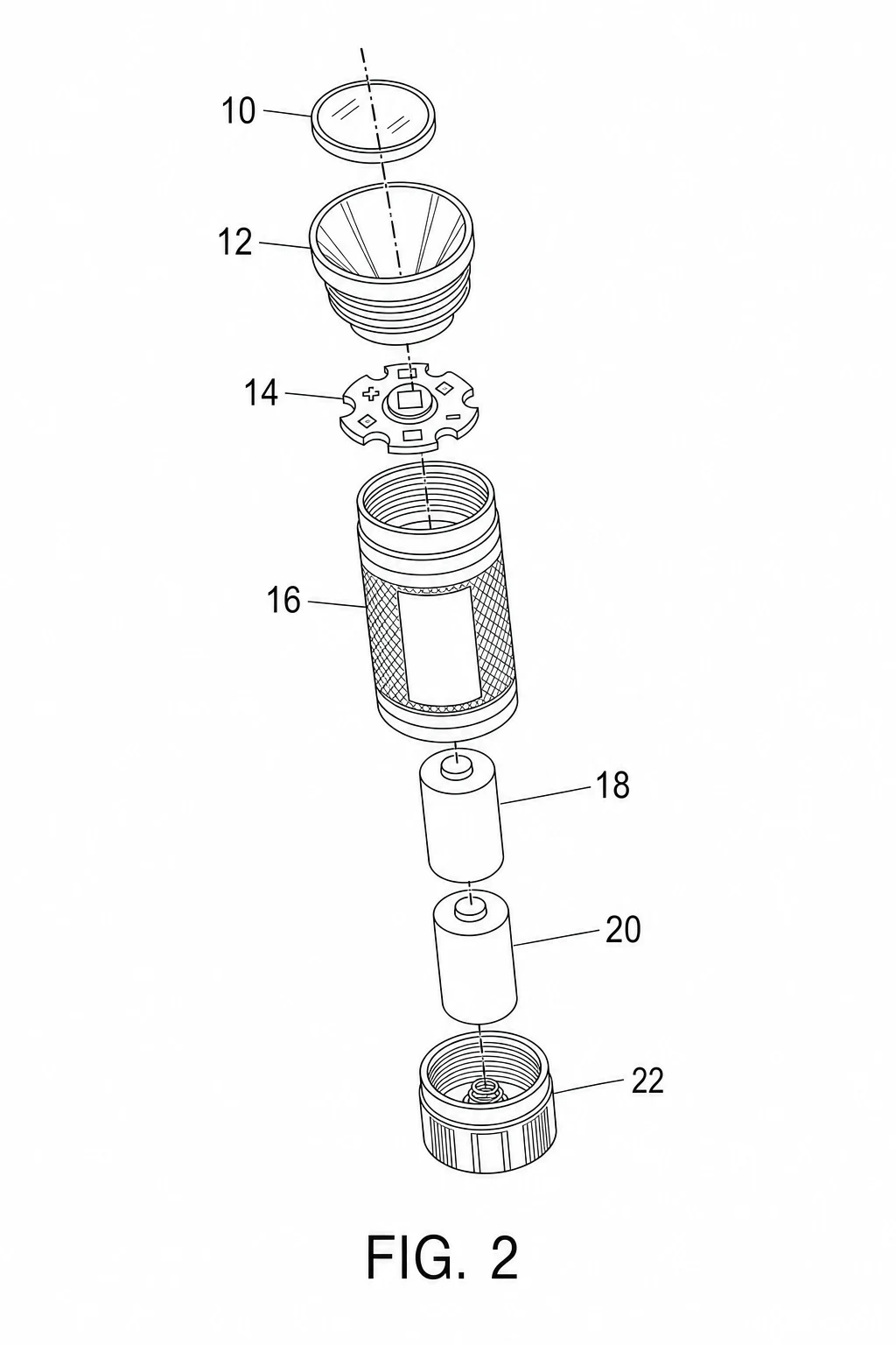
FIG. 2 Exploded View
Parts separated in assembly order and grouped by a bracket, as the rule for exploded views asks. No center line is drawn.
FIG. 3 Method Flowchart
A method claim drawn as boxes and arrows. Step numerals sit outside the boxes on short lead lines.
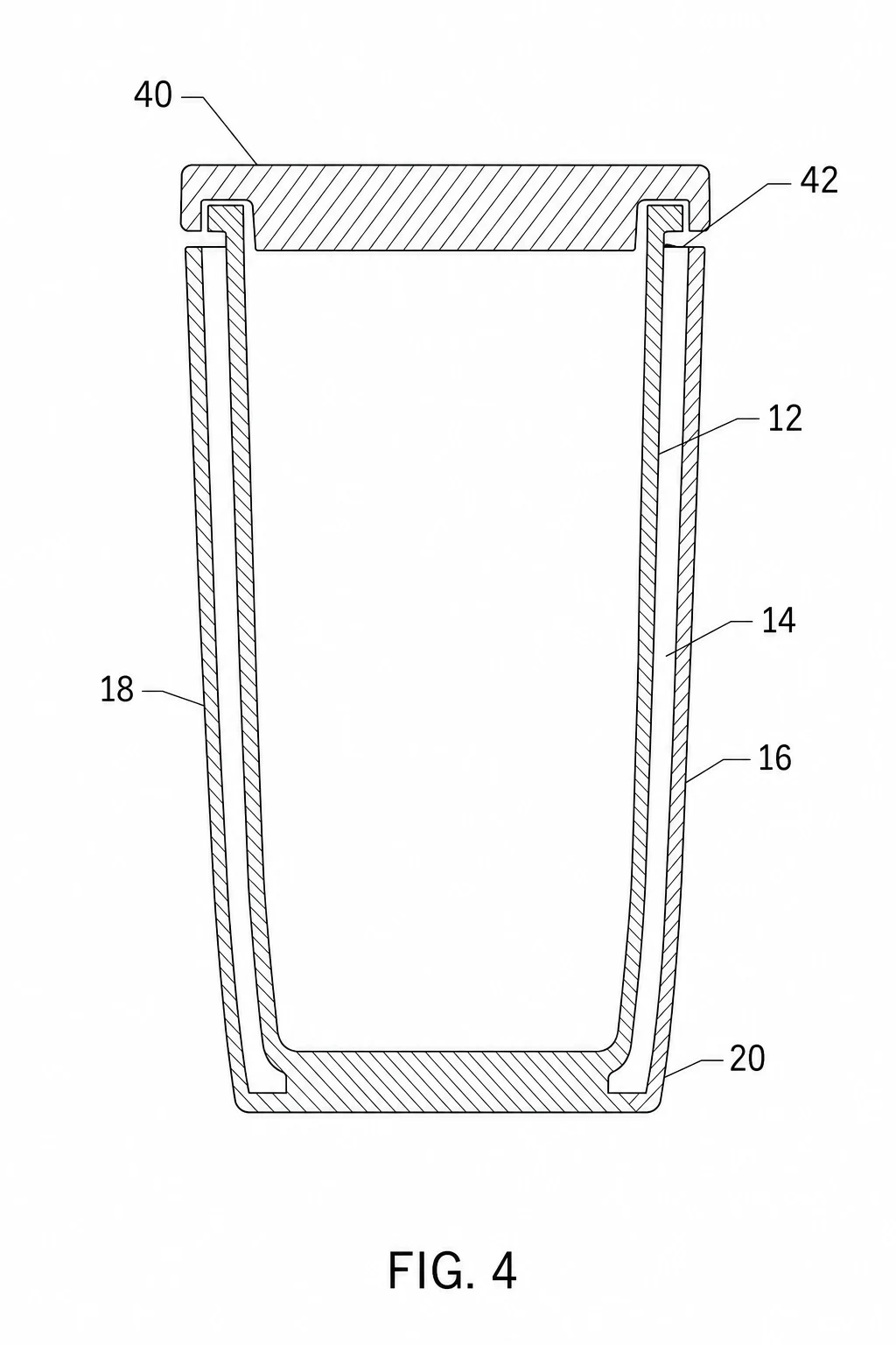
FIG. 4 Cross-Section (needs fixes)
Good hatching on the cut walls, but two fixes are needed: the outer wall carries two numerals (16 and 18), and the lid hatching runs the same direction as the walls.
Review Example: Center Line to Remove
An earlier draft that drew a dash-dot center line through the parts. Views must not contain center lines, so this one was regenerated as FIG. 2.
USPTO drawing rules: what the AI handles and what you check
Each row maps a rule in 37 CFR 1.84 to what the generator does and what still needs a human review. Rules checked against the eCFR on October 7, 2026. The test sheets on this page were generated with the same drawing instructions the tool adds to your description.
| Rule | What it requires | What the generator does | What you check |
|---|---|---|---|
| 1.84(a)(1) Black ink | Utility drawings are normally black and white, in solid black ink. | Prompts force black line art on white. Our test sheets measured as near-pure black and white. | Look for gray shading and soft edges after you resize. Convert to pure black and white if your filing tool asks for it. |
| 1.84(f) and (g) Sheet and margins | Letter (8.5 x 11 in) or A4 sheets. Margins at least 2.5 cm top and left, 1.5 cm right, 1.0 cm bottom. No frame around the drawing. | Outputs a portrait image with white space and no border. It does not produce a sized sheet. | Place each figure on a Letter or A4 page with the required margins before you export the PDF. |
| 1.84(h) Views | Views must not be joined by projection lines and must not contain center lines. Exploded parts are grouped by a bracket. | The prompt asks for no center lines or projection lines, and supports a bracket for exploded views. | Center lines can still slip in. Our first exploded draft had one (shown below). |
| 1.84(h)(3) Sections | Cut surfaces use regularly spaced oblique hatching. Different parts in one section are hatched in different directions. | Draws 45 degree hatching on cut material and leaves hollow spaces white. | Check that touching parts are hatched at different angles. In our FIG. 4 test the lid and walls ran the same way. |
| 1.84(l) Line quality | Lines must be uniformly thick, black, and well defined so they copy cleanly. | Clean, even outlines at the default high quality setting. | Zoom to 100% and redraw any broken or faint lines. |
| 1.84(p) Reference numerals | At least 0.32 cm (1/8 in) tall, not circled, and the same part keeps the same numeral in every view. | Adds plain upright numerals outside the object and follows numerals you name in the prompt. | Match every numeral to your specification. AI can give one part two numerals, as in our FIG. 4 test. |
| 1.84(q) Lead lines | Lead lines run from the numeral to the feature, are as short as possible, and must not cross each other. | Draws short straight lead lines that touch the part. | Confirm each line ends on the right feature, not on a neighbor or in empty space. |
| 1.84(u) Figure numbers | Views are numbered "FIG. 1", "FIG. 2" and so on, larger than the reference numerals. A single view has no figure number. | Places the FIG. label you give it, centered below the drawing. | Renumber in order across all sheets, and delete the label if your application has only one view. |
Sources: 37 CFR 1.84 Standards for drawings, 37 CFR 1.152 Design drawings, and MPEP 608.02 Drawing. This page is general information, not legal advice.
What is a patent drawing?
A patent drawing is a black-and-white technical figure that shows every feature of an invention named in the claims. US utility applications follow the drawing rules in 37 CFR 1.84: plain black lines, reference numerals that point to each part, numbered figures (FIG. 1, FIG. 2), and no decorative color or text. Examiners use the figures together with the written description, so a numeral in the drawing must match the same part in the specification. Most applications need several views of the same object, such as a perspective view, an exploded view of the assembly, and a cross-section through the parts that matter.
What this generator does well, and where you still need a human
- Fast first drafts: describe the object and its parts and get a clean line drawing in under a minute, instead of waiting days for the first sketch.
- The look examiners expect: black outlines on white, numerals outside the object on short lead lines, and a FIG. label below the view.
- Many view types from text: perspective, exploded with a bracket, side or top elevation, cross-section with hatching, block diagrams, and method flowcharts.
- It does not measure or design: proportions are visual, not dimensioned, and fine details can be invented or dropped. Check every feature against your claims.
- It cannot guarantee compliance: treat each output as a draft for your patent attorney, agent, or draftsperson, who confirms the final sheets meet the rules.
How to describe your invention for a usable figure
- Start with the figure number and the view: "FIG. 2: an exploded perspective view of..." The tool uses that label and view type.
- List each part in plain words, in the order a reader would see it. If your specification already assigns numerals, put them in the prompt, for example "lid (40), gasket (42)".
- Say what should not appear, such as hidden internal parts or a background surface.
- For section views, say which material is cut and which spaces are hollow, so the hatching lands in the right places.
- Generate, review the result against the checklist above, then adjust the description and regenerate the views that need changes.
Utility drawings vs design patent drawings
Utility patents protect how something works, so the figures explain structure and function with numerals and lead lines. Design patents protect only how something looks, and follow 37 CFR 1.152 in addition to 1.84: the views must fully show the appearance, surface shading shows shape, broken lines can show parts that are not claimed, and reference numerals are usually not used. This generator is tuned for utility-style figures. You can still draft design views by asking for front, back, left, right, top, bottom, and perspective views with surface shading and no numerals.
From draft to filing
Use the generator early, while the invention is still being described. Inventors use it to explain an idea to their attorney, provisional filers use it to get figures into a first application, and draftspersons use it to block out views before redrawing in CAD. Before filing, place each figure on a Letter or A4 page with the required margins, number the sheets, and run the checklist above. Downloads include a 300 DPI print JPEG. If you want to clean up lines in a vector editor, paid plans and credit packs can also export an SVG trace of the figure.
Frequently Asked Questions
Related Diagram Tools
 Diagrams
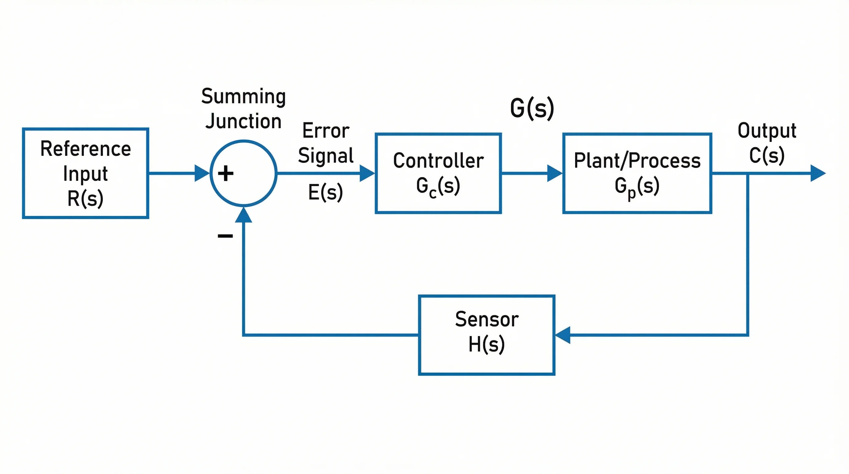
Block Diagram Generator
Turn a system into a labeled block diagram of components and signal flow.
 Diagrams
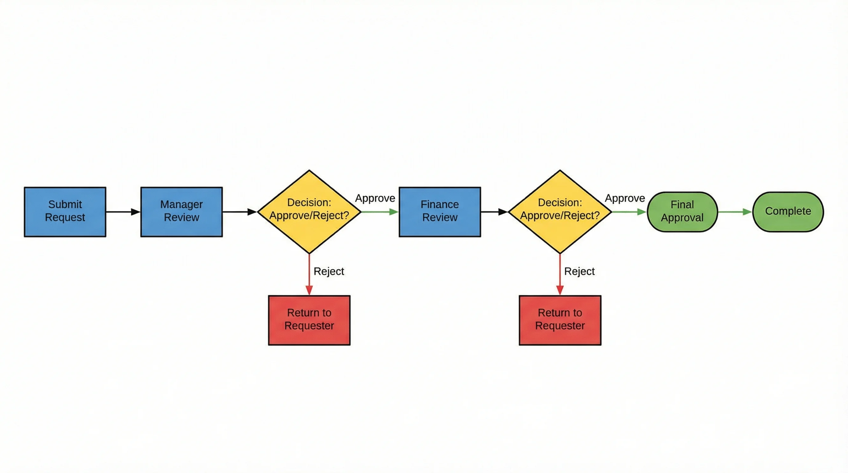
AI Flowchart Generator
Describe a process and get a clean flowchart with decisions and branches.
 Diagrams
Schematic Diagram Maker
Draw labeled schematics of apparatus, circuits, and lab setups.