P&ID Symbols and PFD Equipment Chart
Free P&ID and PFD symbols chart: 53 original vessel, pump, valve and instrument symbols in ISA 5.1 style. Download any symbol as SVG.
53 symbols shown. Click any symbol to enlarge it, download SVG or PNG, or copy the SVG.
Vessels and columns
Pumps and compressors
Heat transfer
Separation and solids
Valves
Instruments
Lines and connectors
Special
Not part of ISA/ISO; our convention for algae and bioprocess drawings.
Need a full drawing, not a legend? Generate a P&ID or a process flow diagram .
Printable P&ID and PFD symbols cheat sheet
Four landscape sheets cover every symbol on this page. Pick A4 or US Letter, color or black and white, then download or print.
Sheet
Paper (landscape)
Printing
Scroll sideways on small screens. PNG downloads are about 300 dpi for the chosen paper.
How to read an instrument bubble
ISA 5.1 splits a tag into a measured variable and a function. The first letter is what you measure. The letters after it say what the device does. The outline of the bubble says where that function lives: a plain circle is field-mounted, a circle with a bar is on the panel (a solid bar is the main accessible console; a dashed bar is behind the panel or inaccessible; a double bar is an auxiliary location), a circle in a square is a DCS shared display, and a diamond inside a square is a PLC.
| Tag | Meaning |
|---|---|
| FIC | Flow indicating controller — shows flow and sets a control valve. |
| LT | Level transmitter — measures liquid level and sends a signal. |
| PI | Pressure indicator — a local gauge, usually field-mounted. |
| TIC | Temperature indicating controller — shows temperature and drives a valve or heater. |
| PDI | Pressure differential indicator — shows the difference between two taps. |
| LAH | Level alarm high — a high-level alarm, not a controller. |
| FT | Flow transmitter — measures flow and sends it to a controller. |
| PT | Pressure transmitter — measures pressure and transmits it. |
PFD vs P&ID: which drawing uses which symbols
Use a process flow diagram when you need the big picture: feed, major units, products, and recycle, with stream numbers that point at a data table. Use a P&ID when you need to build or operate the plant. PFDs usually show only major equipment, main lines and key control valves/loops; P&IDs show every valve, instrument and line. The equipment outlines on this page belong on both.
What this symbol chart covers
- This chart collects original line drawings in the style used by ISA 5.1 (instrument bubbles, valves, and line types) and ISO 10628 (equipment outlines). The standards themselves are not copied. Treat every mark as a teaching convention. A real job follows the legend printed on that project’s drawings.
Equipment tags you will see next to a symbol
Process equipment uses a letter and a number, such as P-101 or T-200. Prefixes on this page: P- for pumps, K- for compressors (some sites use C-), T- or V- for tanks and vessels, C- or T- for columns, E- for exchangers, and R- for reactors. Instruments use the ISA letter code in the bubble (FT, LIC, PSV). Type a prefix such as P- or FT into the search box to find every symbol that uses it.
How to use the downloads
Click a card to enlarge the drawing. Download SVG when you need a crisp vector for a slide, a worksheet, or a draft P&ID — the file has a transparent background. Download PNG when you need a bitmap with a white background. Copy SVG puts the markup on the clipboard so you can paste it into a vector editor. The printable sheets use the same drawings as the cards. Nothing here is gated: no account and no credits.
Sources and what this chart does not cover
All symbols are drawn from scratch for this page after public teaching material for ISA 5.1 and ISO 10628. The standards are paid documents and are not reproduced here. Piping fittings, specialty valves, hydraulic and capillary lines, and company-specific marks sit outside this set. For a controlled drawing, use the current edition of the standard named in the job specification and the project legend. These SVGs are free to download for study, drafts, and teaching.
Frequently Asked Questions
Related Engineering Tools
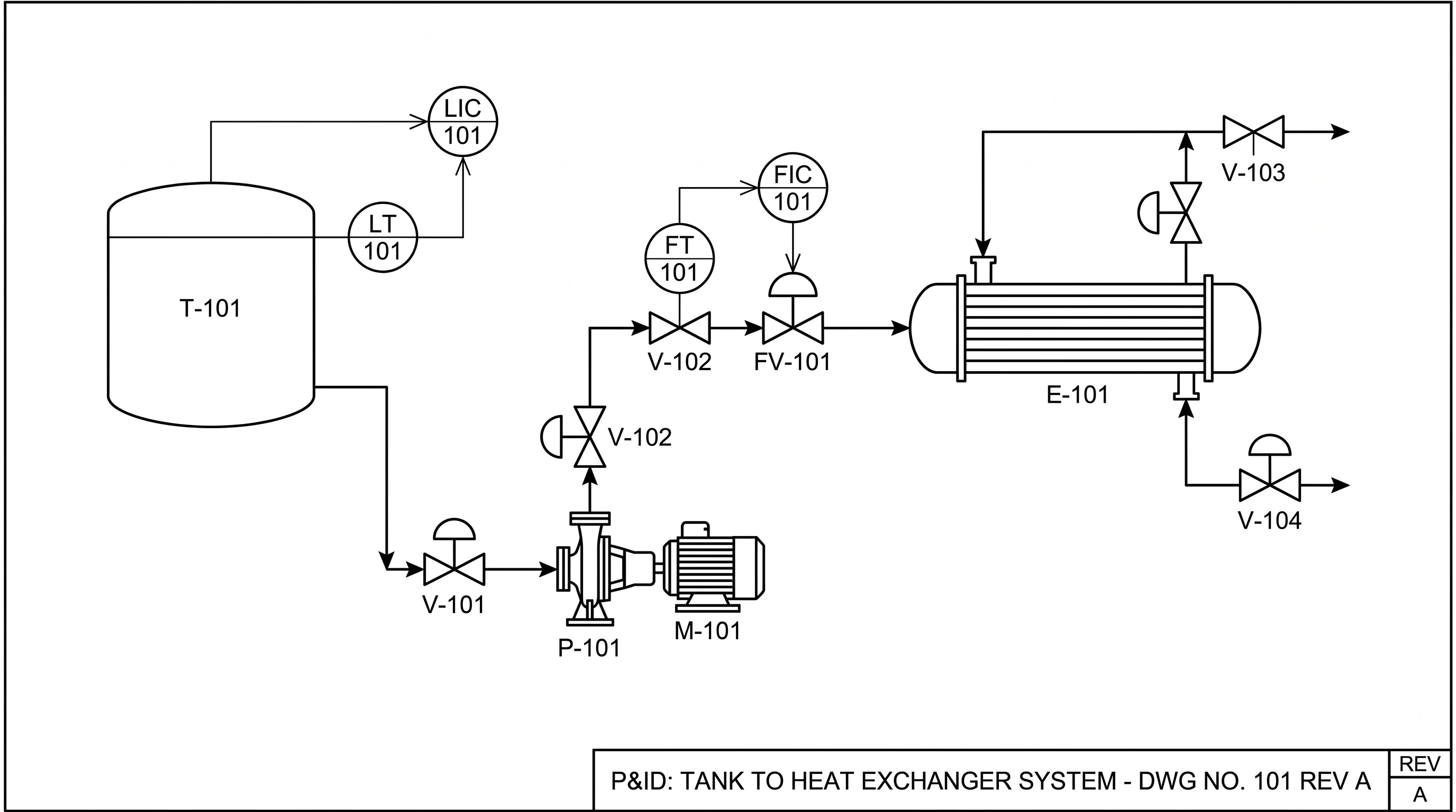 Engineering
P&ID Maker
Create piping and instrumentation diagrams with ISA symbols and instrument tags.
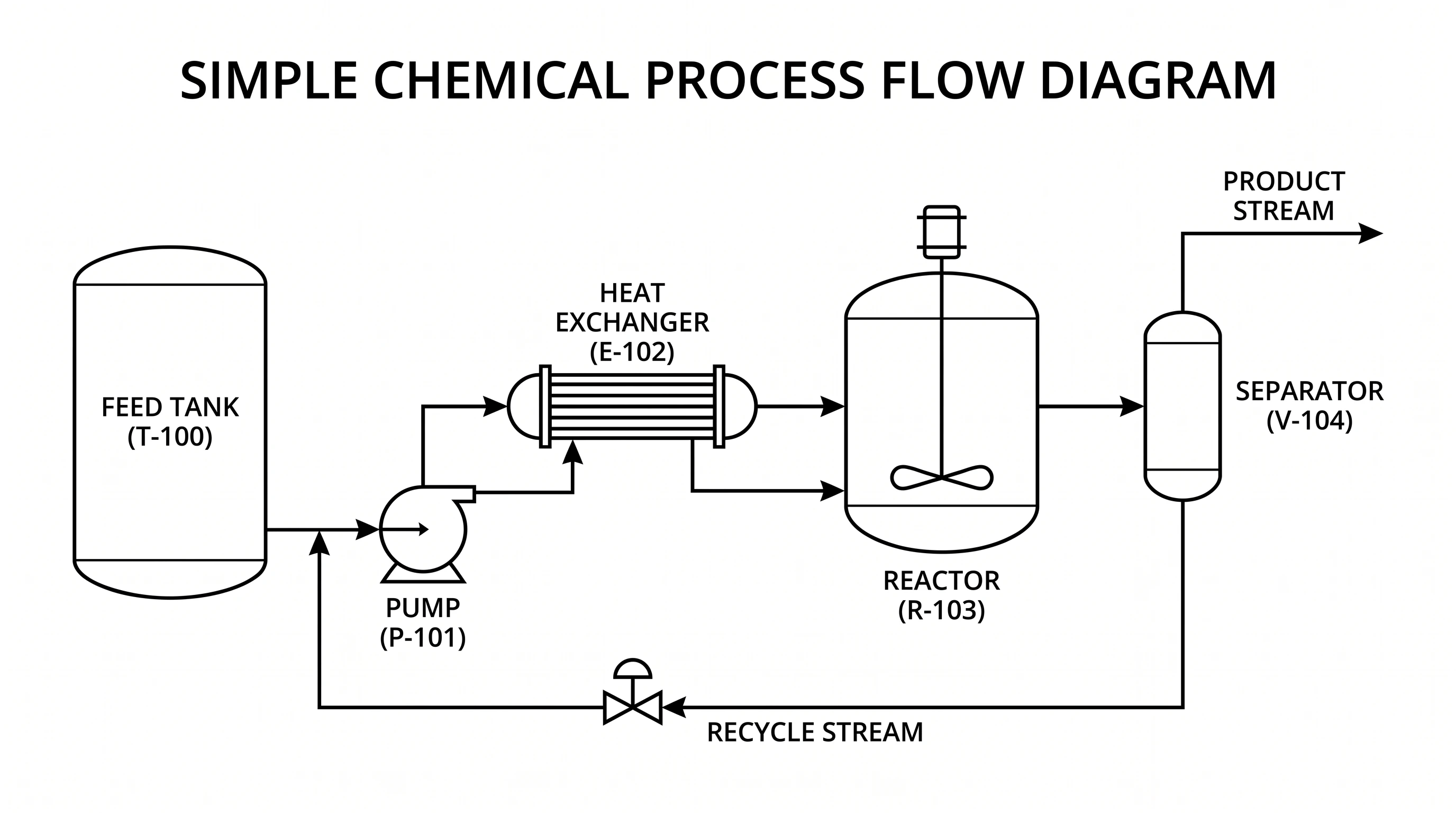 Engineering
Process Flow Diagram Generator
Create a PFD of tanks, pumps, reactors, and columns with labeled streams.
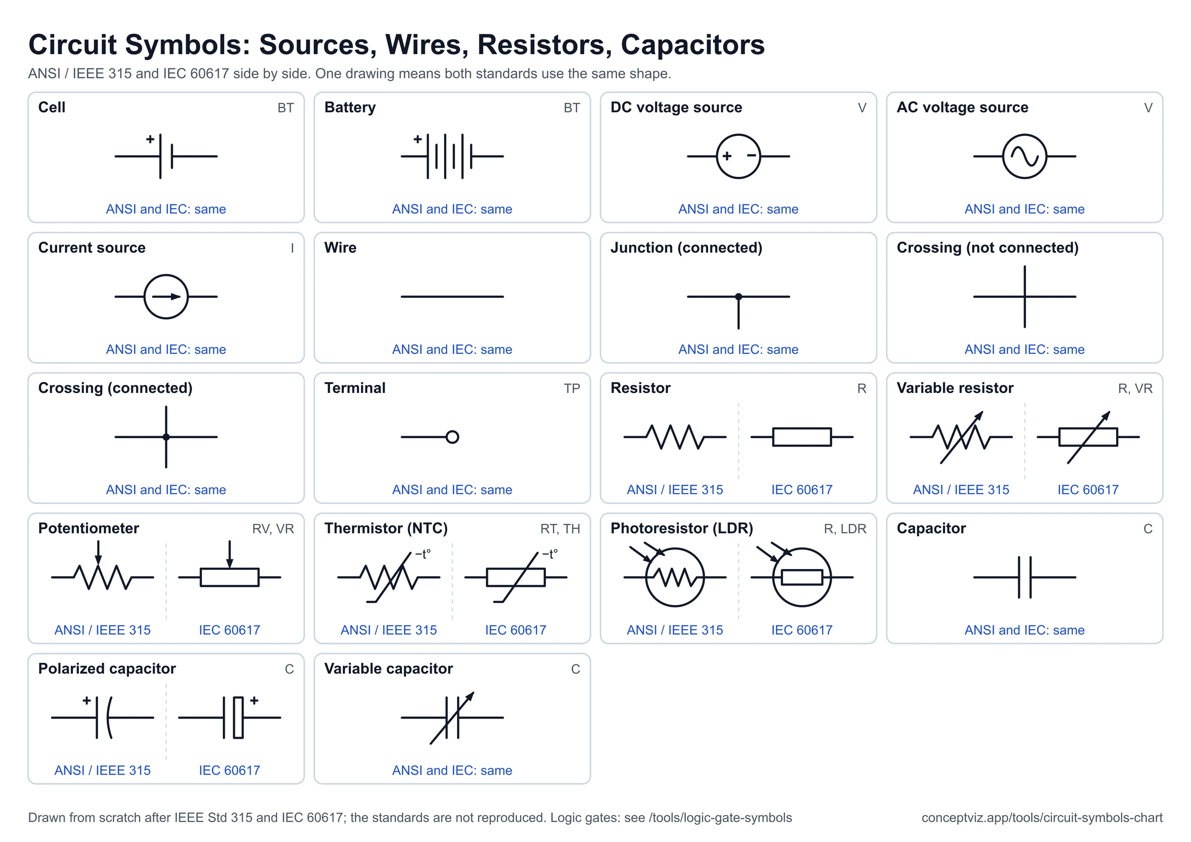 Engineering
Circuit Symbols Chart
Electrical symbols in ANSI and IEC styles with SVG downloads.
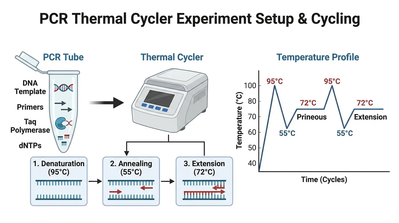 Research
Schematic Diagram Maker
Generate schematic diagrams for lab equipment and experimental apparatus.
 Engineering
Single-Line Diagram Generator
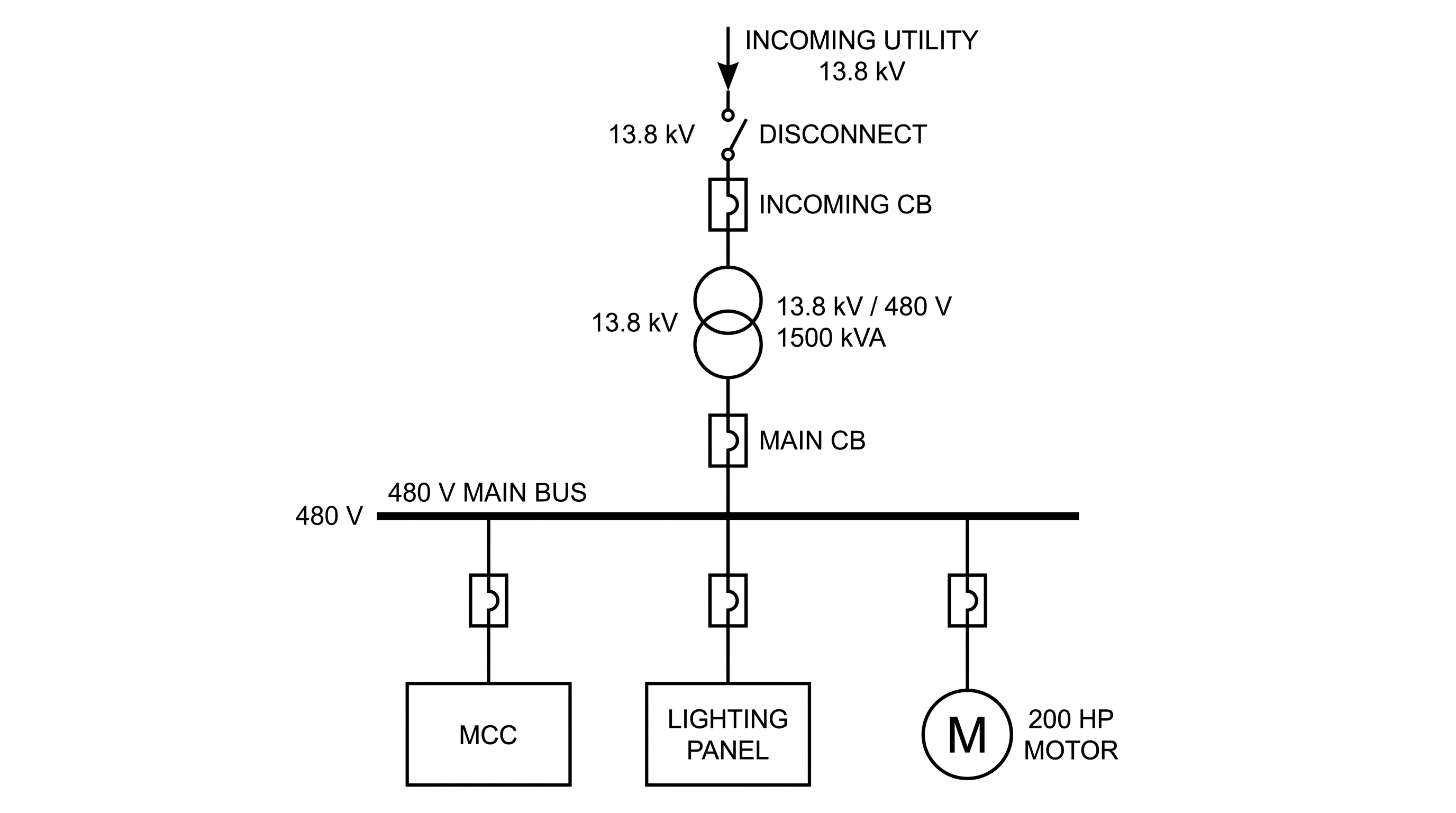
Create electrical single-line diagrams of utility, transformers, and loads.
 Engineering
Block Diagram Generator
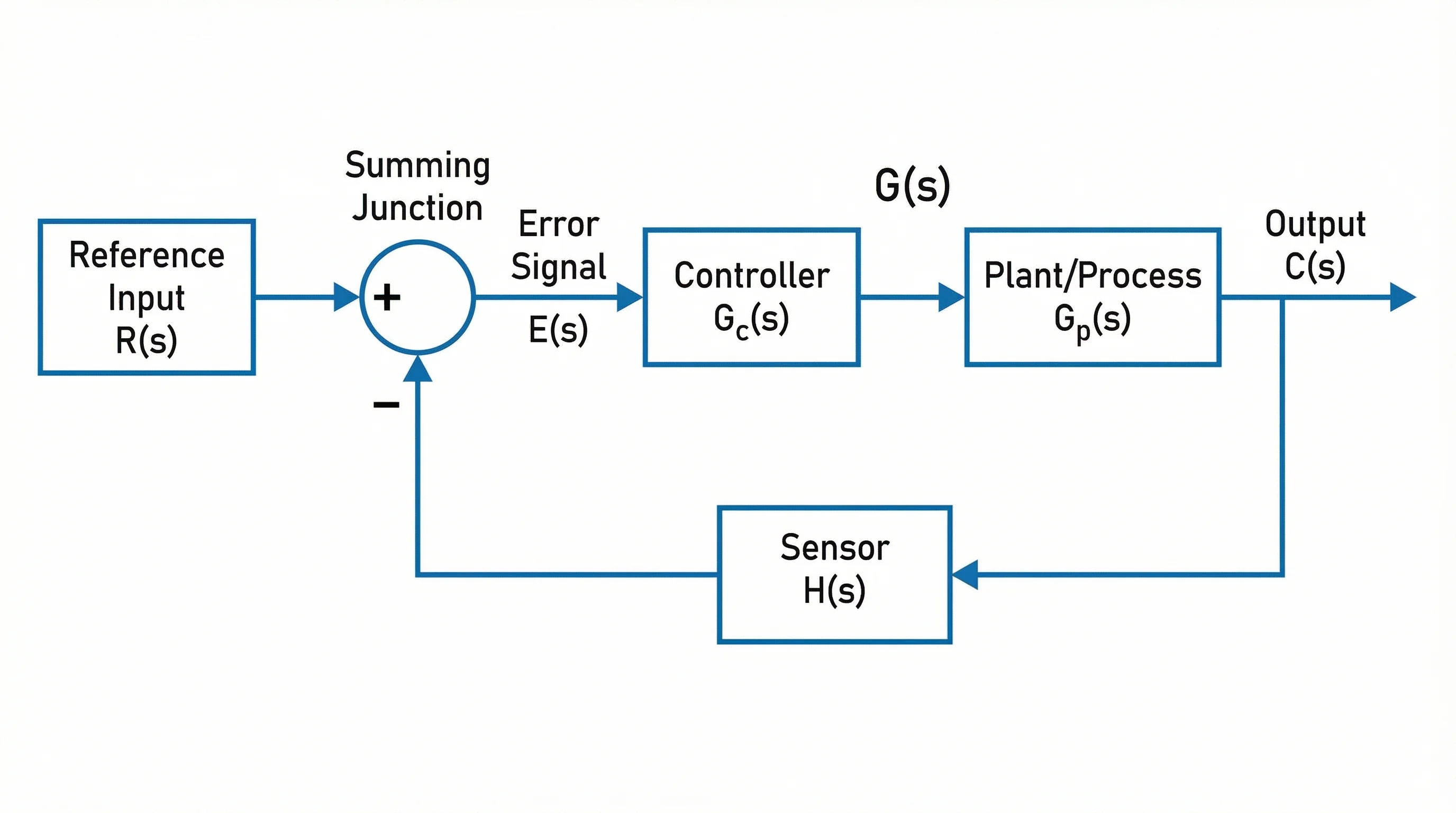
Create block diagrams for control systems, signal paths, and architecture.