Patent Drawing Examples: 8 Figure Types and Objections
See what each type of patent drawing looks like, from exploded and section views to circuits and design views, and why examiners object to figures.
Most people searching for patent drawing examples want the same thing: to see what a finished figure looks like before they draw their own. A perspective view, an exploded view, a flowchart, a circuit, a design patent view: each type follows slightly different rules, and each has its own habitual mistakes.
This guide shows one example of every common figure type, says what the USPTO rule behind it requires, and points out what is wrong with each example. Five figures come from our patent drawing generator gallery (one is an earlier draft kept as a bad example), three more were generated for this article with the same prompt template, and two are exact diagrams we drew ourselves. Every figure is shown with its flaws. Each figure is numbered as if it sat on its own sheet, so the FIG. numbers do not run in order across this page.
Rule text was checked against the current 37 CFR 1.84 on eCFR in October 2026. This is general information, not legal advice. The USPTO decides whether a sheet is acceptable, and a registered patent attorney or agent should review your figures before you file.
Patent Drawing Generator
Describe the view you need and get a black-and-white first draft with a FIG. label, reference numerals, and lead lines. Check it against the rules, then finish it or hand it to a drafter.
Draft a patent figure →The 8 figure types at a glance
| Figure type | What it shows | Main rule | A classic objection |
|---|---|---|---|
| Perspective view | The whole object in 3D | 1.84(h) | Numeral lead line lands on the wrong part |
| Exploded view | Parts separated in assembly order | 1.84(h)(1) | Center line drawn through the parts |
| Section view | A cut through the object | 1.84(h)(3) | Neighboring parts hatched the same way |
| Method flowchart | The steps of a process | 1.84(o) | Too much text inside boxes |
| Block diagram | Components and how they connect | 1.83(a) | A claimed connection is missing or wrong |
| Circuit schematic | Electrical elements with standard symbols | 1.84(n) | Symbols with no recognized meaning, elements not identified in the specification |
| Chemical formula | A structure as its own figure | 1.84(d) | Formula not labeled as a separate figure |
| Design patent views | Appearance from every side | 1.152 | Missing views, hidden planes shown |
What a patent drawing has to do
Two rules sit behind everything below. First, for a nonprovisional application, the drawing must show every feature of the invention specified in the claims, and conventional features can be shown as a graphical symbol or a labeled box. Second, the format rules in 37 CFR 1.84 decide whether the sheet can be reproduced and read: black and white drawings are normally required (1.84(a)(1)), color is accepted in design applications and in utility applications only after a petition (1.84(a)(2)), and every line, number, and letter must be clean, dark, and uniformly thick and well-defined, though different thicknesses are allowed where they carry different meaning (1.84(l)).
A word on vocabulary: examiners object to drawings, while claims are rejected. An objection to a drawing usually means you must submit corrected sheets. That is annoying but fixable, and the fix cannot add anything new, because 35 USC 132(a) bars new matter. Corrected figures go in as replacement sheets under 37 CFR 1.121(d).
1. Perspective view
A perspective (or isometric) view shows the whole object at once and is often Figure 1. Because one of the views should be suitable for printing on the front page of the patent (1.84(j)), so it is often the figure readers see first.
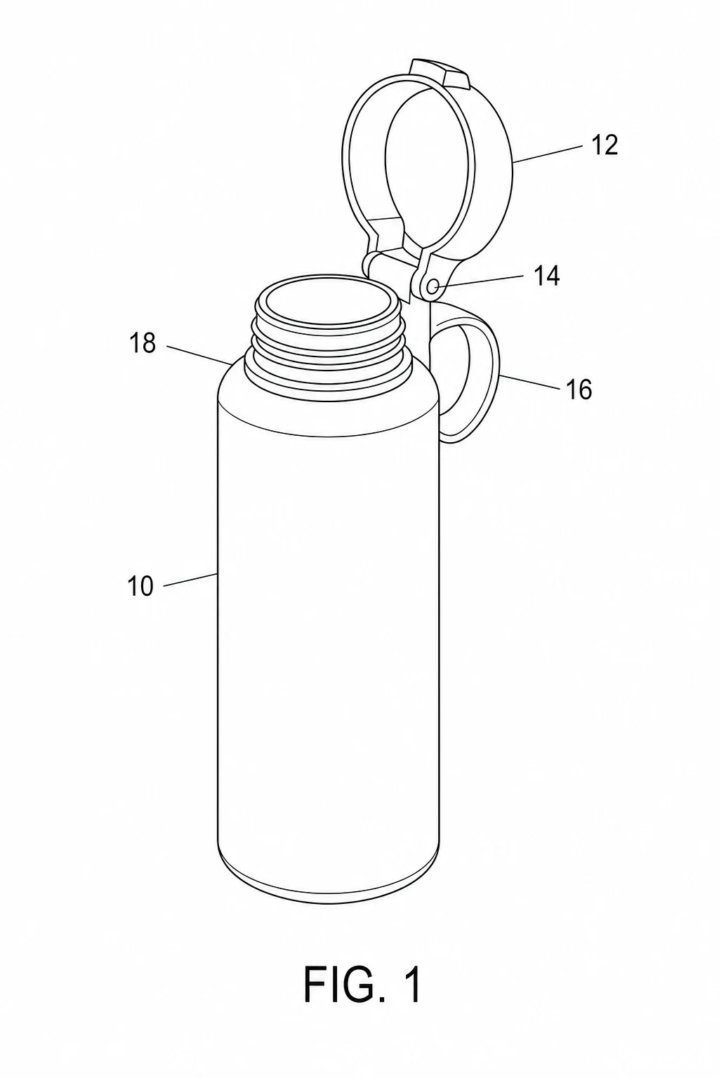
Perspective view from our generator gallery, unedited. Numerals 10 to 18 sit outside the object on short lead lines that touch the part. Check: the lid (12), hinge pin (14), loop (16), and neck threads (18) each have one numeral, and the background is a very light gray (measured 252 to 254 out of 255), not pure white. Convert it to pure black and white before filing.
What to check on yours: each part keeps one numeral in every view (1.84(p)(4)), numerals are plain and at least 0.32 cm tall (1.84(p)(3)), and no numeral appears that the description never mentions (1.84(p)(5)).
2. Exploded view
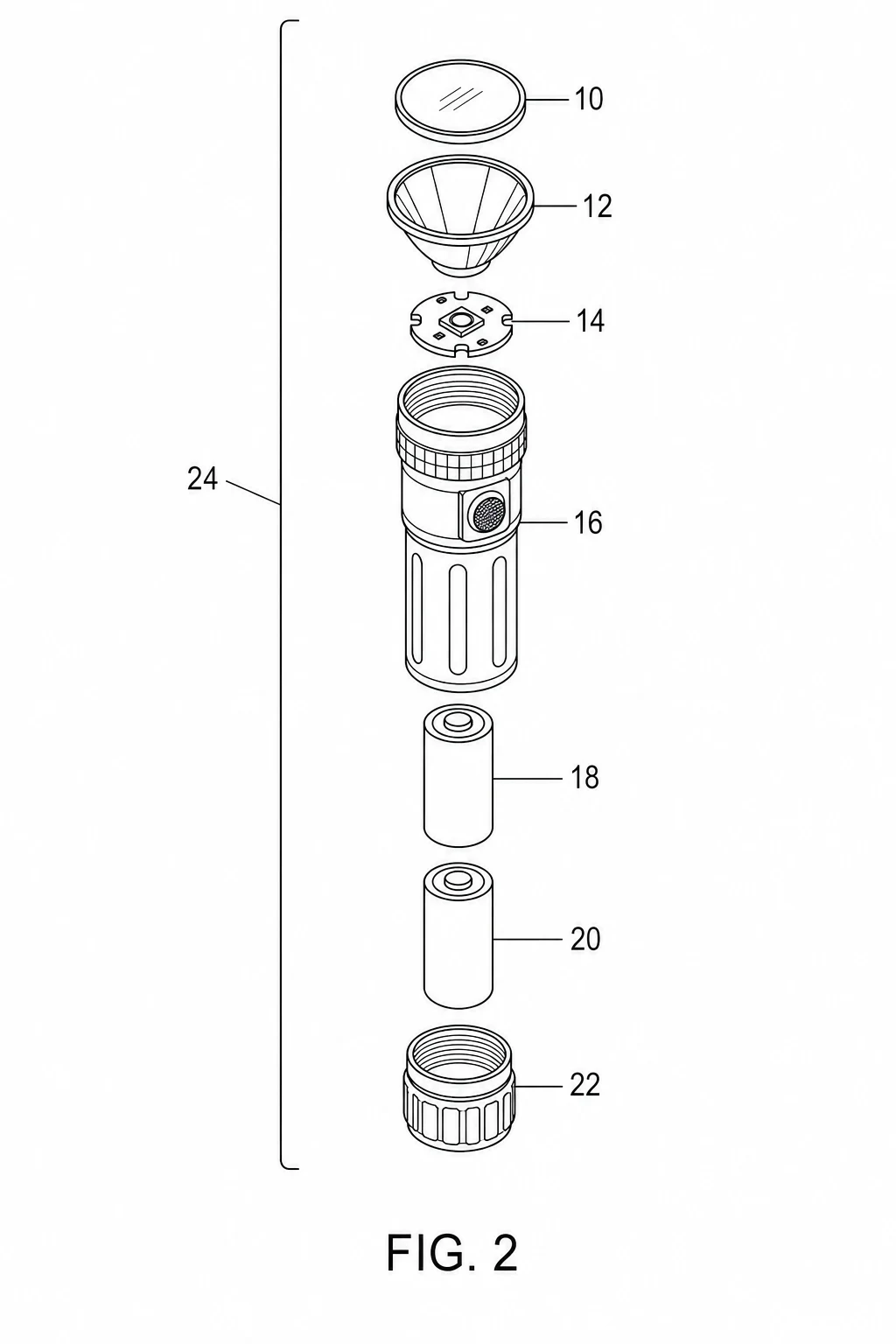
An exploded view pulls the parts apart along their assembly path so each one can be seen. The rule asks for the separated parts to be embraced by a bracket to show their relationship or order of assembly (1.84(h)(1)).
Exploded view from our generator gallery, unedited. The bracket (24) embraces the separated parts and each has its own numeral, 10 to 22. Check: the batteries are drawn as plain cylinders, so confirm the cell type, polarity, and the spring or contact details match your actual design.
This is also where a typical generator mistake shows up. Our first attempt at this same figure ran a dash-dot center line through every part, which 1.84(h) does not allow, since views must not contain center lines:
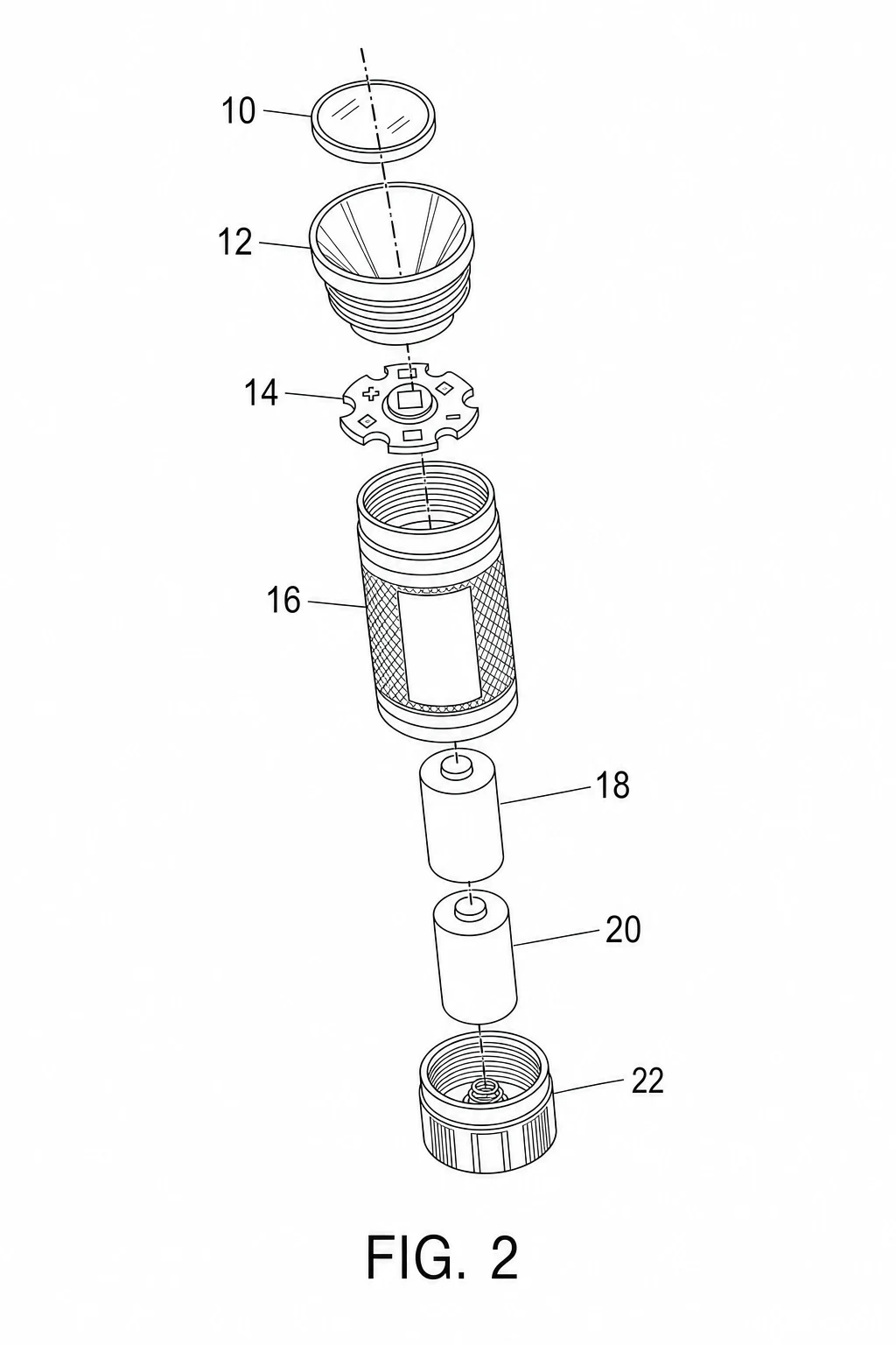
The earlier draft with the center line, kept as an example of what to remove. We added "no center lines" to the prompt template and regenerated, which produced the figure above.
3. Section (cross-section) view
A section view shows the inside of an object along a cutting plane. The plane should be indicated on the view it is cut from, cut surfaces use regular oblique hatching, and the hatching of juxtaposed different elements must be angled in a different way (1.84(h)(3)).
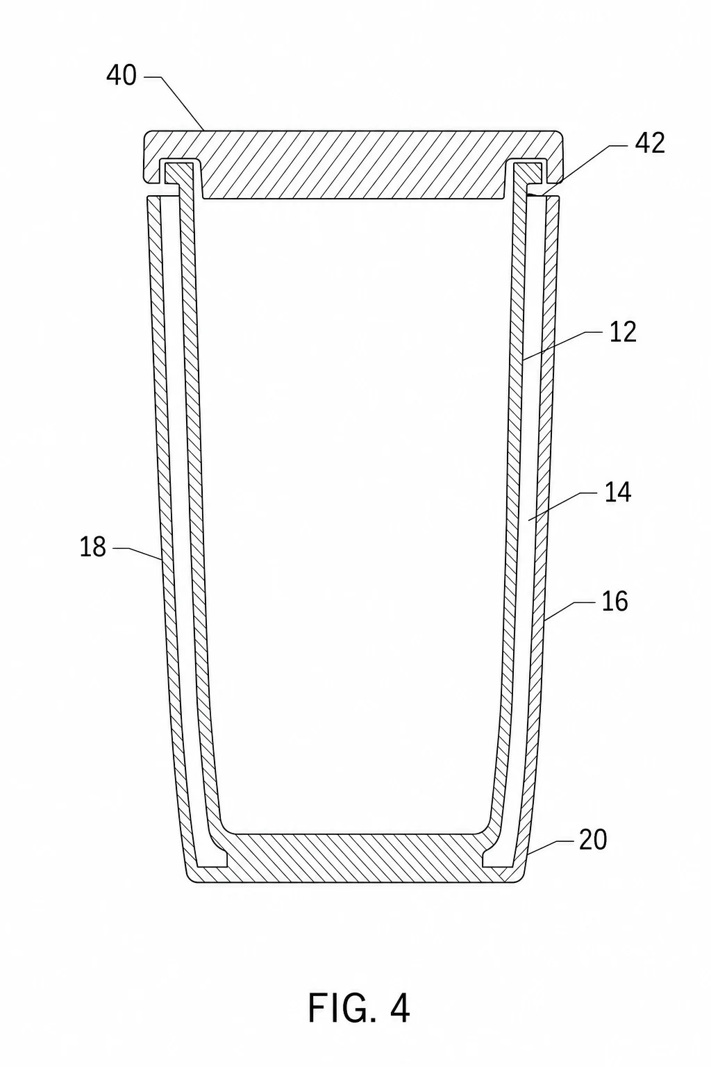
Section view from our generator gallery, unedited, and it needs fixes. The outer wall carries two numerals, 16 on the right and 18 on the left, which breaks the one-part-one-numeral rule, and the lid hatching runs the same direction as the outer wall on the right where the two meet, while the (h)(3) sentence above asks for juxtaposed elements to be hatched in different directions. Both are quick edits, but you have to notice them.
In our example, the section view needed the most human attention, because the hatching rule is a relationship between neighboring parts, not a property of one part.
4. Method flowchart
A method claim is usually drawn as boxes and arrows. Words inside boxes are allowed as legends, but they "should contain as few words as possible" (1.84(o)), and if you number the steps, each numeral must appear in the description and vice versa (1.84(p)(5)).
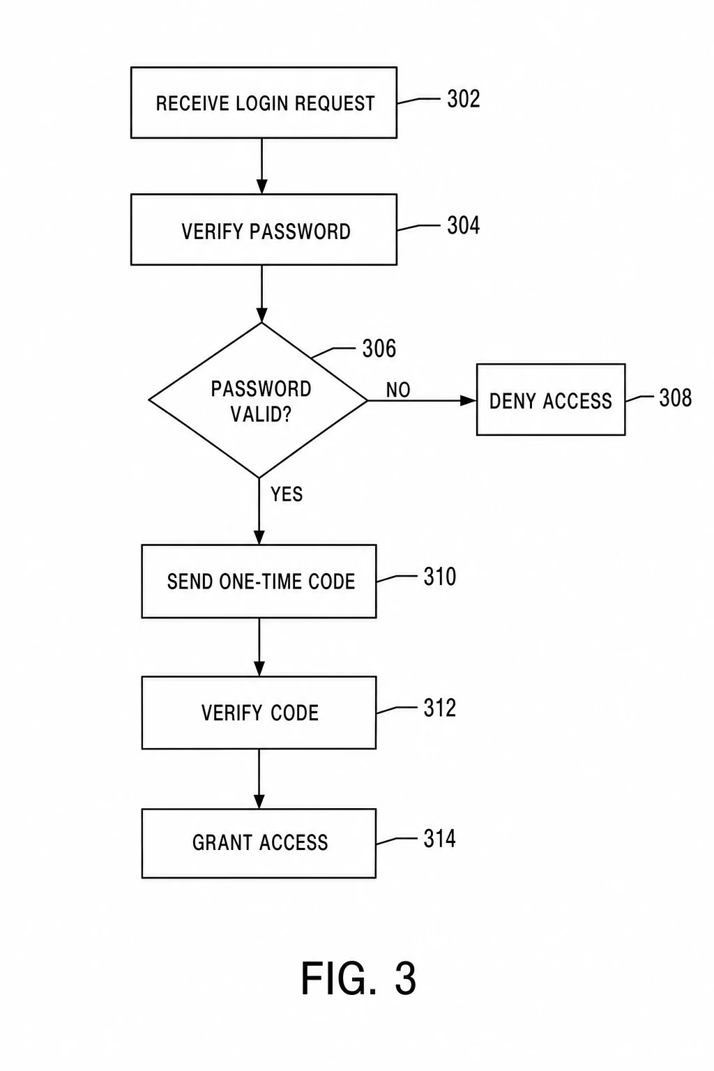
Method flowchart from our generator gallery, unedited. Steps 302 to 314 each have a numeral on a short lead line, and the YES and NO branches are labeled. Check: arrows must reflect the real order of your method, and the step text must match your claim language.
For a flowchart, arrows are not decoration. Under 1.84(r) an arrow at the end of a line can show direction of movement, so every arrow is a statement about your process. For more on structuring these, see our block diagram guide.
5. Block (system) diagram
A block diagram shows components as labeled boxes and the connections between them. It is the standard way to show software and electronics architecture when the exact circuitry is not claimed, and the rule for conventional features allows "a labeled representation" (1.83(a)).
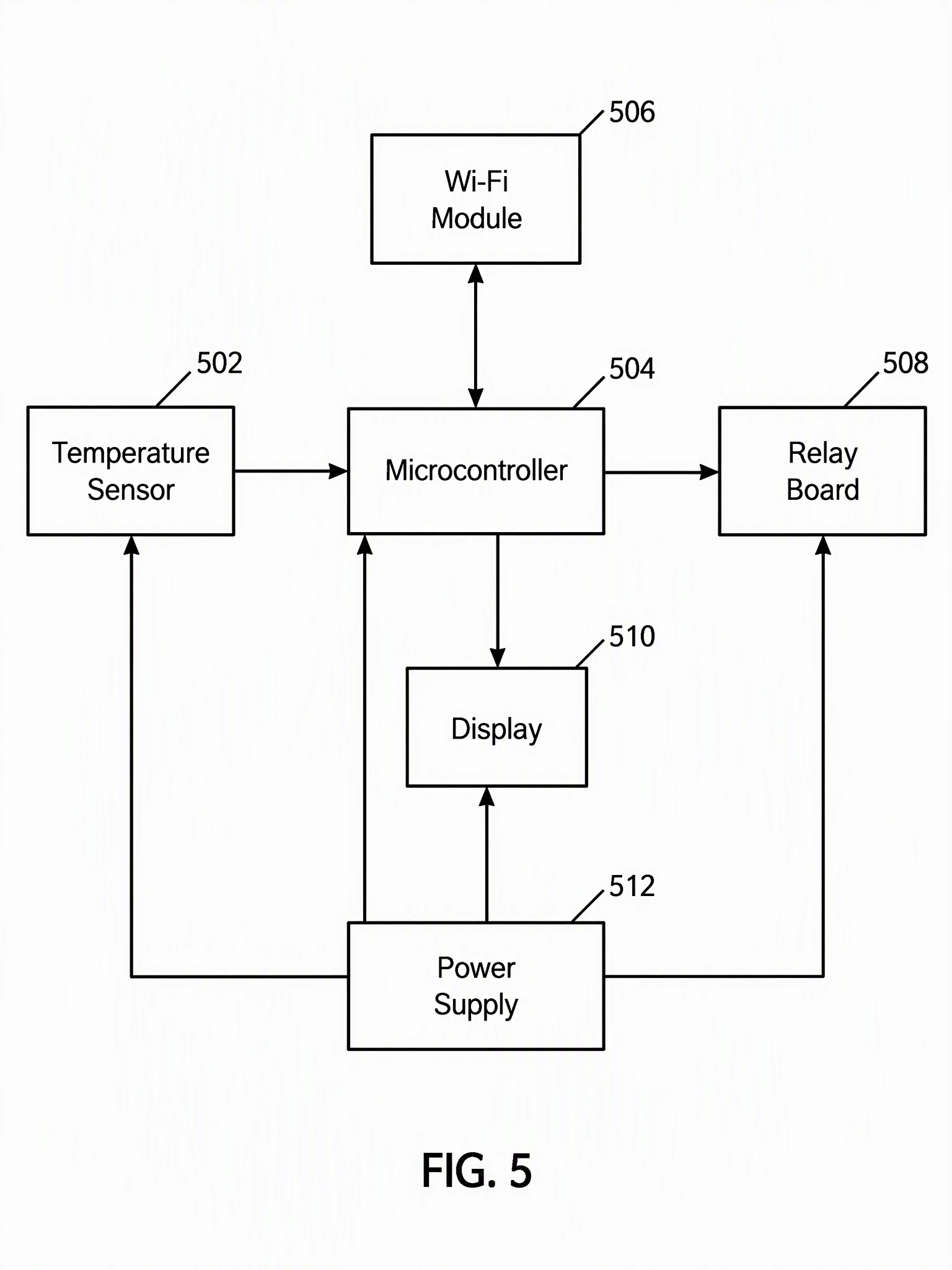
Block diagram generated for this article, unedited. Prompt (inserted into the generator's USPTO-style template): a smart thermostat with temperature sensor 502, microcontroller 504, Wi-Fi module 506, relay board 508, display 510, and power supply 512, with sensor to microcontroller, microcontroller to Wi-Fi (two-way), relay, and display, and power supply to each of the other five blocks. What came out: all six numerals and the signal arrows are correct, but the power supply has no line to the Wi-Fi module, so only four of the five requested power connections were drawn. The background also carries faint ghost strokes (visible beside the Wi-Fi box) on top of the light gray (252 out of 255), which need cleaning.
That missing line is the typical block diagram failure: it looks complete and a missing connection is invisible unless someone checks every pair of blocks. A figure that omits a connection your claims rely on is a drawing problem under 1.83(a), not a cosmetic one.
6. Circuit schematic
A schematic uses standard symbols for electrical elements. Rule 1.84(n) allows graphical drawing symbols for conventional elements, says the elements must be adequately identified in the specification, and asks for symbols with a universally recognized conventional meaning where they exist.
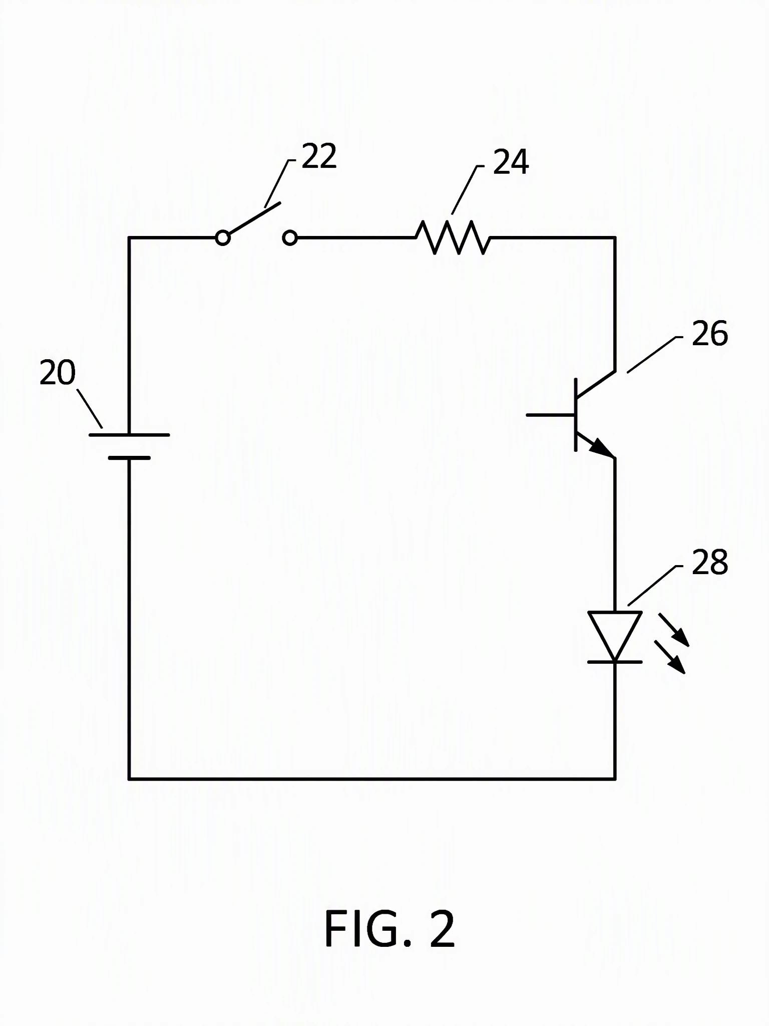
Schematic generated for this article, unedited. Prompt: a battery 20, switch 22, resistor 24, transistor 26, and LED 28 in series with standard symbols. The symbols themselves are conventional and the numerals are readable, but the transistor's base terminal is left unconnected, so as drawn the circuit would not work. That is partly our prompt (we asked for a plain series loop and gave the transistor no control signal), and it is exactly the kind of error to expect: a generator draws what the words say, not what the circuit needs. The switch is also drawn open, and the lead line for 26 ends beside the collector terminal rather than on the symbol, and the lead lines for 24 and 28 also end just short of their symbols. The background has faint ghost strokes on both sides on top of the light gray, which need cleaning.
Do not use an AI schematic as an engineering document. It is a layout for you or a drafter to correct. For circuit drawing tools and the symbol conventions, see our schematic diagram guide and the circuit diagram maker.
7. Chemical formula
Formulae can be submitted as drawings and are subject to the same requirements (1.84(d)). Each chemical or mathematical formula must be labeled as a separate figure, using brackets when necessary. Structures are one place where we do not recommend AI image generation at all: a wrong bond or atom changes the compound, so we drew this one deterministically.
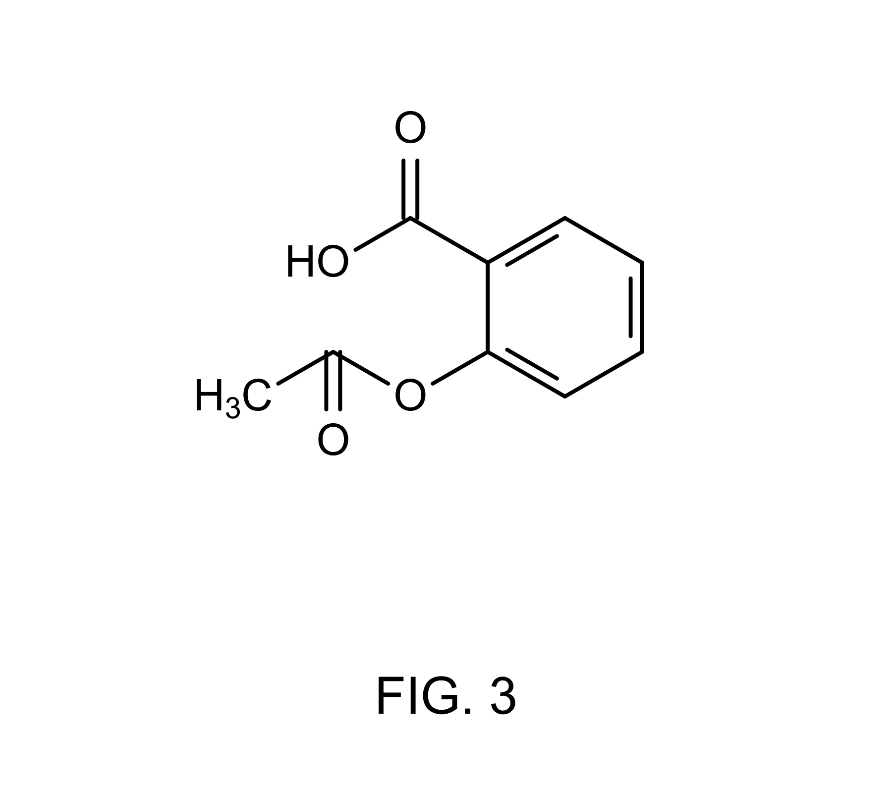
Structure of acetylsalicylic acid (aspirin) drawn with a short script of ours, so every bond and atom label is exact. Black line art on a white background, with a FIG. 3 label. This is a teaching example, not a filing sheet: letter height depends on the final sheet scale, and 1.84(p)(3) asks for at least 0.32 cm.
If you need many structures, a dedicated chemistry editor is the right tool. Our chemistry structure generator is aimed at classroom-style structures; for a patent, draw the structure in a chemistry editor you trust and check every atom against your description.
8. Design patent views
A design patent protects how an article looks, so the drawing is the claim. 37 CFR 1.152 requires "a sufficient number of views to constitute a complete disclosure of the appearance of the design," asks for surface shading to show contour, and bars solid black shading except to represent the color black as well as color contrast. Broken lines may show visible environmental structure that is not claimed, but may not show hidden planes. Design drawings also usually carry no reference numerals, but that is practice, not text in 1.152.
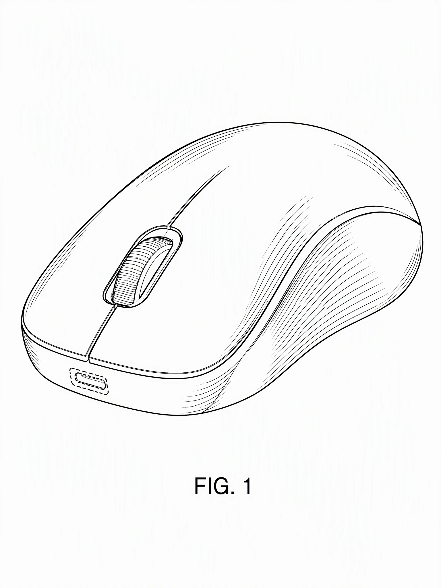
Design view generated for this article, unedited. Prompt: an ornamental perspective view of a computer mouse with fine contour shading lines only, no numerals, and the cable port as a dashed broken line. The result has contour lines, no numerals, and a dashed port. Its flaws: it is a single perspective view, and a design application usually needs several views (often the six standard sides) so the appearance is completely disclosed. The dense contour lines on the right come close to solid black, which 1.152 does not allow. The background is light gray (252 out of 255) rather than pure white, with faint ghost strokes around the mouse, so it needs cleaning too. Whether the dashed port is the right choice is a claim-scope decision for your attorney, because everything solid is claimed and everything dashed is not.
Design figures are the least forgiving, because shading choices and the number of views define scope. If a design matters commercially, pay a professional design-patent drafter.
Why drawings get objections
We looked for an official ranked list of the most common drawing objections and did not find one we could cite, so the list below is built straight from the rule text rather than from statistics. Each row links to the sentence it comes from.
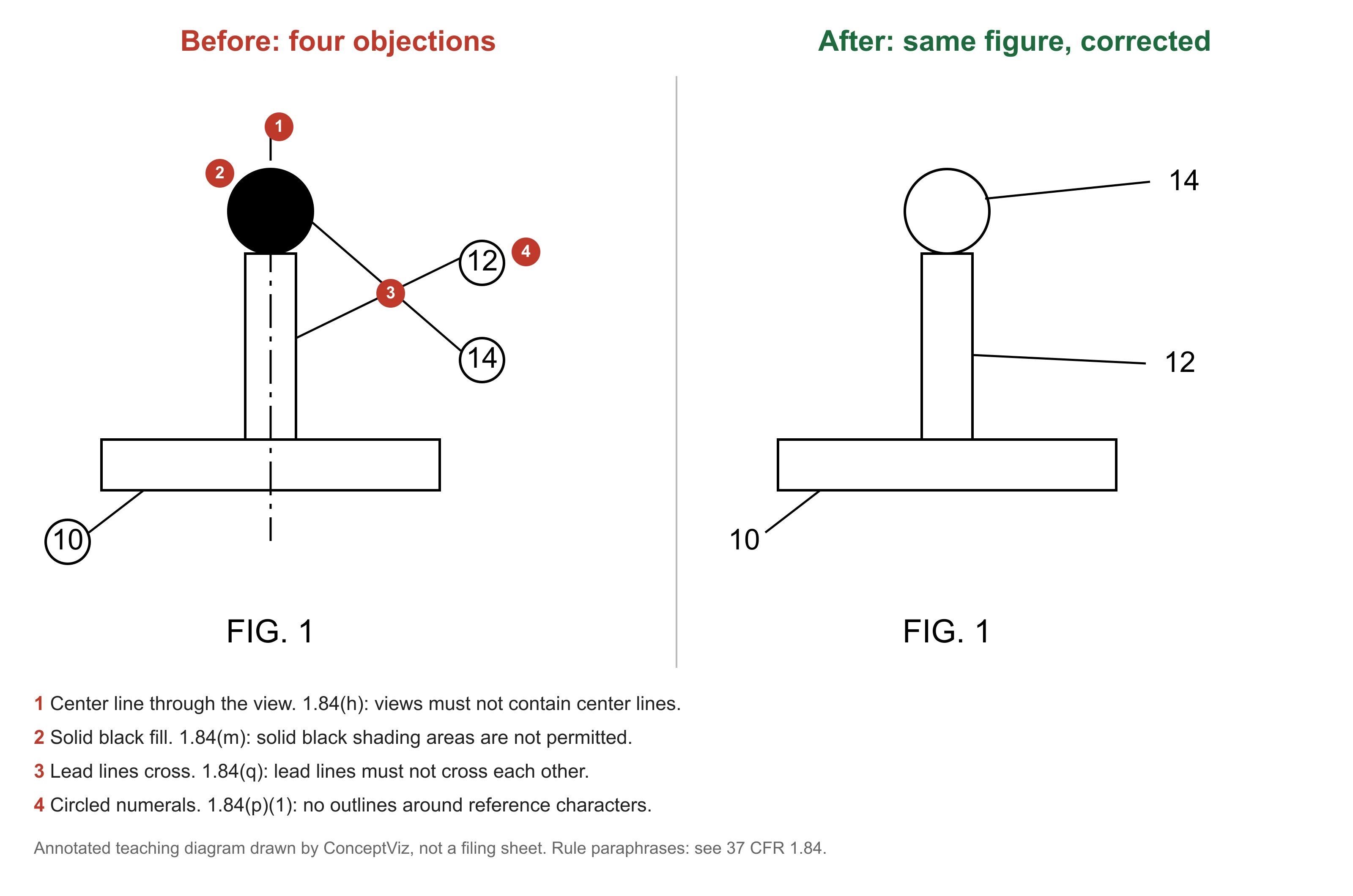
An exact diagram drawn by us, not a filing sheet. The left figure carries four objections, the right figure fixes them.
| Problem on the sheet | What the rule says | Where |
|---|---|---|
| Center line or projection line in a view | Views must not be connected by projection lines and must not contain center lines | 1.84(h) |
| Solid black areas | Solid black shading areas are not permitted, except for bar graphs or color | 1.84(m) |
| Lead lines that cross | Lead lines must not cross each other | 1.84(q) |
| Circled or bracketed numerals | Reference characters must not be enclosed in outlines such as circles | 1.84(p)(1) |
| Numerals too small | At least 0.32 cm | 1.84(p)(3) |
| Same part, different numeral | A part must always carry the same reference character | 1.84(p)(4) |
| Numeral missing from the description | Characters not mentioned in the description shall not appear in the drawings | 1.84(p)(5) |
| Figures not numbered "FIG." | View numbers are consecutive Arabic numerals preceded by "FIG." | 1.84(u) |
| Frame around the sheet, wrong margins | No frames around the sight, set margins | 1.84(g) |
| Faint or crowded figure | Must stay readable when reduced to two-thirds | 1.84(k) |
| Feature in the claims is not shown | The drawing must show every claimed feature | 1.83(a) |
For the sheet size, margins, and software choices behind these, see Best Patent Drawing Software, which compares ten tools and drafting services with prices checked in October 2026.
Using an AI draft the right way
Across the gallery figures and the three drafts generated for this article, the generator produced black line art, FIG. labels, numerals, and short lead lines in a form that resembles the examples above. It also produced a center line once, a doubled numeral, a missing power connection, and a transistor that is not connected to anything. None of that is visible from the thumbnail.
A workable routine:
- Write the prompt from your description and name every numeral you want.
- Generate, then compare the figure with the description part by part and arrow by arrow.
- Remove anything the rules in the table above rule out, and clean up the faint gray background to pure black and white.
- Give the result to your patent attorney, agent, or drafter as a first draft, not a finished sheet.
Start free with 2 image credits, valid for 7 days, no card required. If you later buy an image pack, you can convert a generated figure to SVG for cleanup, which spends credits. The SVG is a trace of the image, not an editable schematic or CAD file.
Block Diagram Generator
Draft system and signal-flow diagrams from a plain description.
Frequently asked questions
What does a patent drawing look like?
A utility patent drawing is a black and white line figure on a white sheet, with each view labeled FIG. 1, FIG. 2 and so on, plain reference numerals, and short lead lines from each numeral to its part. Design patent drawings look similar but add surface shading and usually have no numerals.
What types of patent drawings are there?
Common types are perspective views, exploded views, section views, method flowcharts, block diagrams, circuit schematics, chemical or mathematical formulas, and, for design patents, a set of views showing the article from every side.
Why do examiners object to patent drawings?
Common objections come from format rules in 37 CFR 1.84, such as center lines, solid black areas, crossing lead lines, circled numerals, numerals too small, or a missing FIG. label, or from a figure that does not show a feature the claims rely on (37 CFR 1.83(a)). An objection usually means you submit corrected sheets without adding new matter.
Do patent drawings have to be in color?
No. Black and white drawings are normally required. Color drawings are permitted in design applications, and the Office accepts them in utility applications only after granting a petition (37 CFR 1.84(a)(2)).
What is different about design patent drawings?
A design patent drawing is the claim itself. 37 CFR 1.152 asks for enough views to fully disclose the appearance, surface shading to show contour, and bars solid black shading except to represent the color black as well as color contrast. Broken lines may show visible unclaimed environment but not hidden planes.
Do provisional applications need formal drawings?
Ask your attorney. Many inventors file provisionals with simple, clear figures, but the drawings still have to show the invention well enough to support the claims you file later, and you cannot add new matter afterward. Following the 37 CFR 1.84 conventions from the start saves redrawing.
Can AI make patent drawings?
AI can produce a first draft of a figure quickly, but every draft needs a human to check the content, such as connections, numerals, and hatching, and the format against 37 CFR 1.84. Nothing here guarantees a sheet will pass review, and a registered patent attorney or agent should review the final figures.
Summary
Each figure type has its own rule and its own habitual error, from center lines in exploded views to missing connections in block diagrams. Check every figure against your description and 37 CFR 1.84, then take it to your patent attorney or agent. For tool choices and prices, see our patent drawing software comparison, or draft your first figure in the patent drawing generator.
Further reading
Categories
More Posts
ER Diagram Guide: How to Design Entity-Relationship Diagrams Step by Step (2026)
Learn how to draw ER diagrams from scratch in this step-by-step guide. Covers Chen and Crow's Foot notation, best practices, real examples, and free tools.
15 Illustration and Infographic Design Styles Explained (2026)
Explore 15 illustration and infographic design styles with examples: flat, isometric, 3D, hand-drawn, minimalist, vector, cartoon, line art and more.
How to Create Scatter Plots in Excel: Step-by-Step Guide (2026)
Learn how to make scatter plots in Excel with trend lines, labels, and formatting. Complete guide with screenshots and tips for research data visualization.