C4 Diagram Generator for Software Architecture
Generate C4 model diagrams from text: System Context, Container, Component, and Code levels, with an exact reference diagram for each. Free to try.
Create Your C4 Diagram
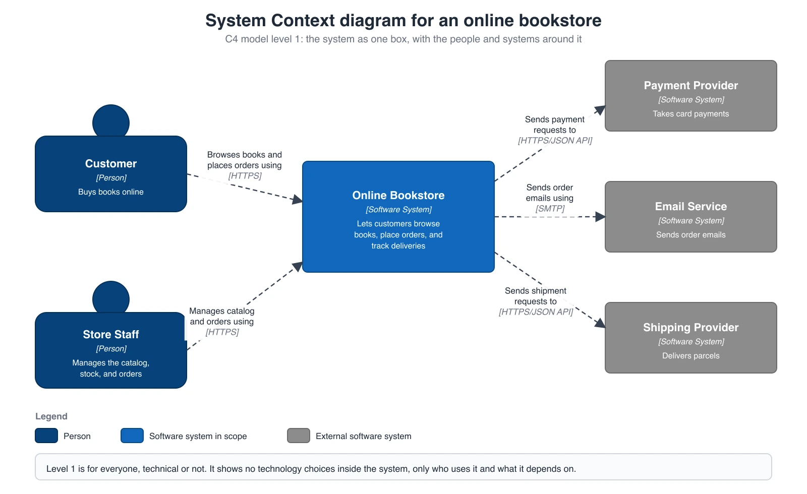 Example: Level 1: System ContextView full size
Free to try ·
Your C4 diagram will appear here
AI diagrams are drafts. Check every element type, arrow, and label before use.
C4 Diagram Examples
One exact diagram per C4 level, drawn in code: System Context, Container, Component, and Code.
System Context diagram: online bookstore
Level 1, drawn in code. The system is one box, surrounded by the people who use it and the external systems it depends on. Every arrow has a verb phrase and the technology in brackets, and there is a legend. The names are fictional.
Container diagram: task management SaaS
Level 2, drawn in code. The system boundary holds a web application, an API application, a database, and a background worker, each with its technology. External systems sit outside the boundary. A container here is a running app or data store, not a Docker container.
Component diagram: API application
Level 3, drawn in code. It zooms into one container, the API application, and shows its components: two controllers, two services, a repository, and a client. Neighboring containers and systems stay outside the boundary.
Code diagram: Task Service classes
Level 4, drawn in code as a UML class diagram, which is the notation the C4 model suggests for this level. It is optional: draw it only for components that need it, or generate it from the source code.
What is a C4 diagram?
A C4 diagram is a software architecture diagram drawn at one of four zoom levels defined by the C4 model: System Context, Container, Component, and Code. Created by Simon Brown, the model uses a small set of shapes (people, software systems, containers, components) and labeled relationships. Most teams draw only the first two levels. This C4 diagram generator drafts levels 1 to 3 from a text description, and the Code level as a UML class diagram.
The four levels of the C4 model
- Level 1, System Context: the whole system as one box, with the people who use it and the other software systems it depends on. It answers “what is this system and who touches it?” and suits everyone, technical or not.
- Level 2, Container: zooms into the system and shows the separately running applications and data stores that it is made of, such as a web app, an API, a database, or a worker, plus the technology of each and how they talk. It suits developers and operations staff.
- Level 3, Component: zooms into one container and shows the main building blocks inside it, such as controllers, services, and repositories. It suits the developers who work on that container.
- Level 4, Code: zooms into one component and shows how it is implemented, usually as a UML class diagram or an entity relationship diagram. The C4 model treats this level as optional, and it is often generated from the code.
Which C4 level should you draw?
- Start with System Context when you are explaining a project to someone new, such as a manager, a customer, or a new hire. Add a Container diagram when people need to see the shape of the system and which technologies it uses. This pair is enough for many teams, and it is what most design documents and architecture reviews need.
- Draw a Component diagram for a container that is complex or that several developers change at once, and only for that container. Draw a Code diagram rarely, for a component whose design is hard to follow from the source alone.
- Each level should be readable on its own. Keep one level per diagram, and do not show components and people in the same picture.
C4 notation: the building blocks
- Person: a human user of the system, such as a customer or an administrator.
- Software system: the highest level of abstraction, something that delivers value to its users. Your own system is the system in scope, and anything you depend on but do not build is an external software system.
- Container: a separately running application or data store, such as a single-page app, an API, a database, a message queue, or a file store. It is not a Docker container, although it can run in one.
- Component: a grouping of related code behind a well-defined interface inside a container, for example a controller, a service, or a repository. A component is not separately deployable.
- Relationship: an arrow with a label. A good label has a short verb phrase (“Reads from and writes to”) and, between containers or systems, the technology or protocol in brackets, such as [HTTPS] or [SQL/TCP].
- Boundary: a dashed rectangle that groups elements, usually the system boundary on a Container diagram or the container boundary on a Component diagram.
C4 diagram vs UML and a regular architecture diagram
- UML is a large, formal notation with many diagram types, and its shapes carry strict meaning. The C4 model is not a notation standard. It is a way to structure diagrams by zoom level, built on a handful of simple boxes and arrows, so it is quick to learn. C4 even suggests UML class diagrams for its Code level.
- A typical hand-made architecture diagram mixes levels: a user, a framework, a database, and a cloud service in one picture, often with no legend. A C4 diagram fixes the level and names every element’s type, so two readers see the same thing.
- For a looser, free-form system view, use the Software Architecture Diagram Generator. For a deployment, network, or sequence view, use a diagram built for that purpose.
Rules that make a C4 diagram readable
- Give the diagram a title that names the type and the scope, for example “Container diagram for Taskly”.
- Give each element a name, a type (Person, Software System, Container, or Component), and a short description. For containers, add the technology.
- Label every arrow with a verb phrase, and add the technology or protocol for calls between containers and systems. Prefer one-direction arrows that show who starts the interaction.
- Add a legend that explains shapes, colors, and line styles. Do not rely on color alone; the boxes also carry their type in text.
- Keep the abstraction level consistent: no component boxes on a Container diagram, and no database tables on a Component diagram.
Beyond the four levels
The C4 model also describes supplementary diagrams. A system landscape diagram shows several systems across a company. A dynamic diagram shows how elements work together for one scenario, in numbered steps. A deployment diagram shows where containers run, such as on servers, in cloud services, or in clusters. Describe these in the prompt as well, and name the type you want.
How to generate a C4 diagram from text
- Name the level first: System Context, Container, Component, or Code.
- List the people and the systems, with a few words about what each one does. For a Container or Component diagram, name the technology of each container.
- Describe the main relationships in words, such as which element calls which, and over what protocol.
- Ask for a legend, a white background, and legible English labels, then check every box and arrow against your real system before you publish.
Exact diagrams vs AI drafts
The four diagrams on this page are drawn in code, so every box, arrow, and label was placed on purpose. Their company and product names are fictional. The generator above creates new drafts with AI, and AI can mislabel an element type, reverse an arrow, or leave a technology off an arrow. Treat every generated diagram as a draft and check it against the system you actually run. Notation reference: c4model.com.
Frequently Asked Questions
For a freer system view that is not tied to C4 levels, use the Software Architecture Diagram Generator. For business context, integrations, and deployment in a proposal, see the Solution Architecture Diagram Generator. For the class diagrams behind the Code level, use the UML Diagram Generator, and for a plain context view outside C4, the Context Diagram Generator.
Source for the C4 model and its notation (checked November 2026): c4model.com.
Related Diagram Tools
 Diagrams
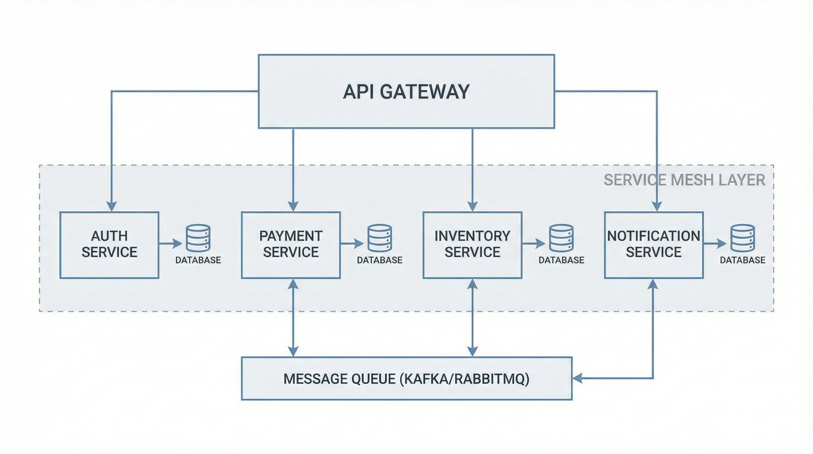
Software Architecture Diagram Generator
Microservices, client-server, cloud, and event-driven system views from a plain-English description.
 Diagrams
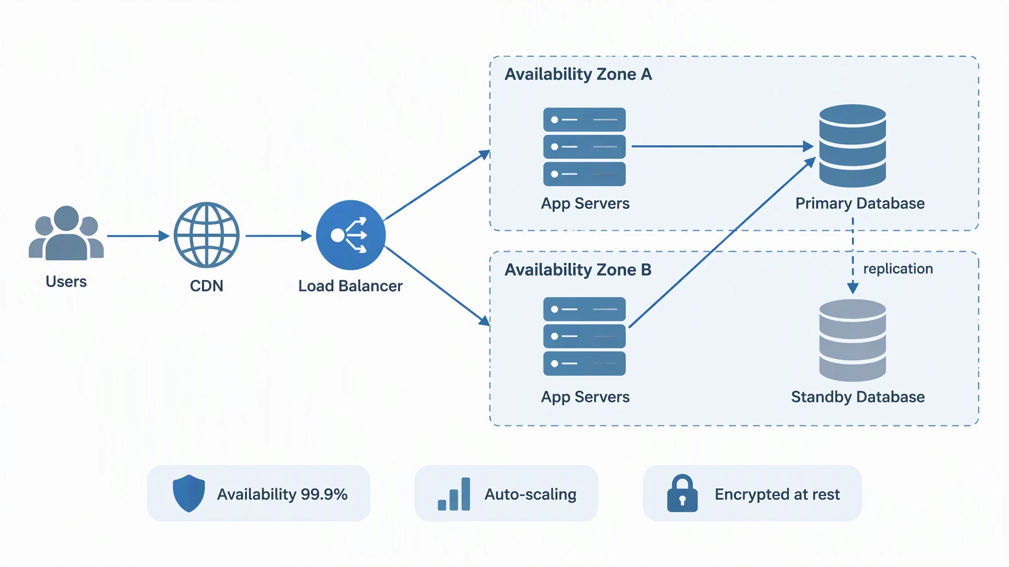
Solution Architecture Diagram Generator
The customer view: business context, integrations, and deployment for proposals and design reviews.
 Diagrams
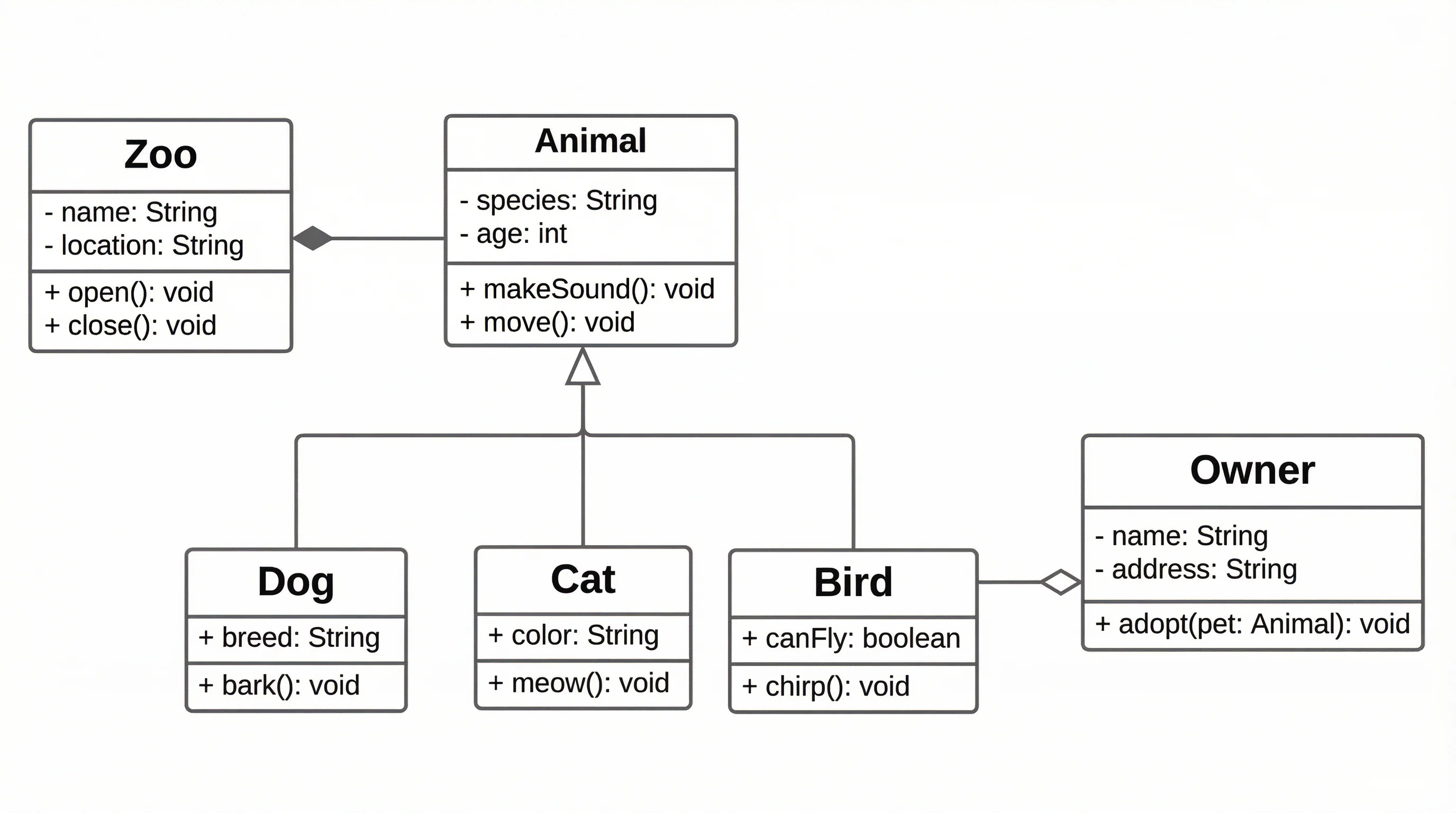
UML Diagram Generator
Create class, sequence, and component UML diagrams to model software structure and behavior.