Wiring Diagram Maker for Electrical Wiring Diagrams
Make a wiring diagram with AI. Describe the system — components, terminals, wire colors, and connections — and get a clean electrical wiring diagram for home, automotive, or appliance projects. Download as PNG.
AI Wiring Diagram Maker
Vista previa gratis en esta página · La descarga del archivo limpio requiere un
Your wiring diagram will appear here
Describe components, terminals, wire colors, and connections
Wiring Diagram Examples
Exact reference diagrams drawn in code from a checked wire list. AI drafts from the generator need checking against them.
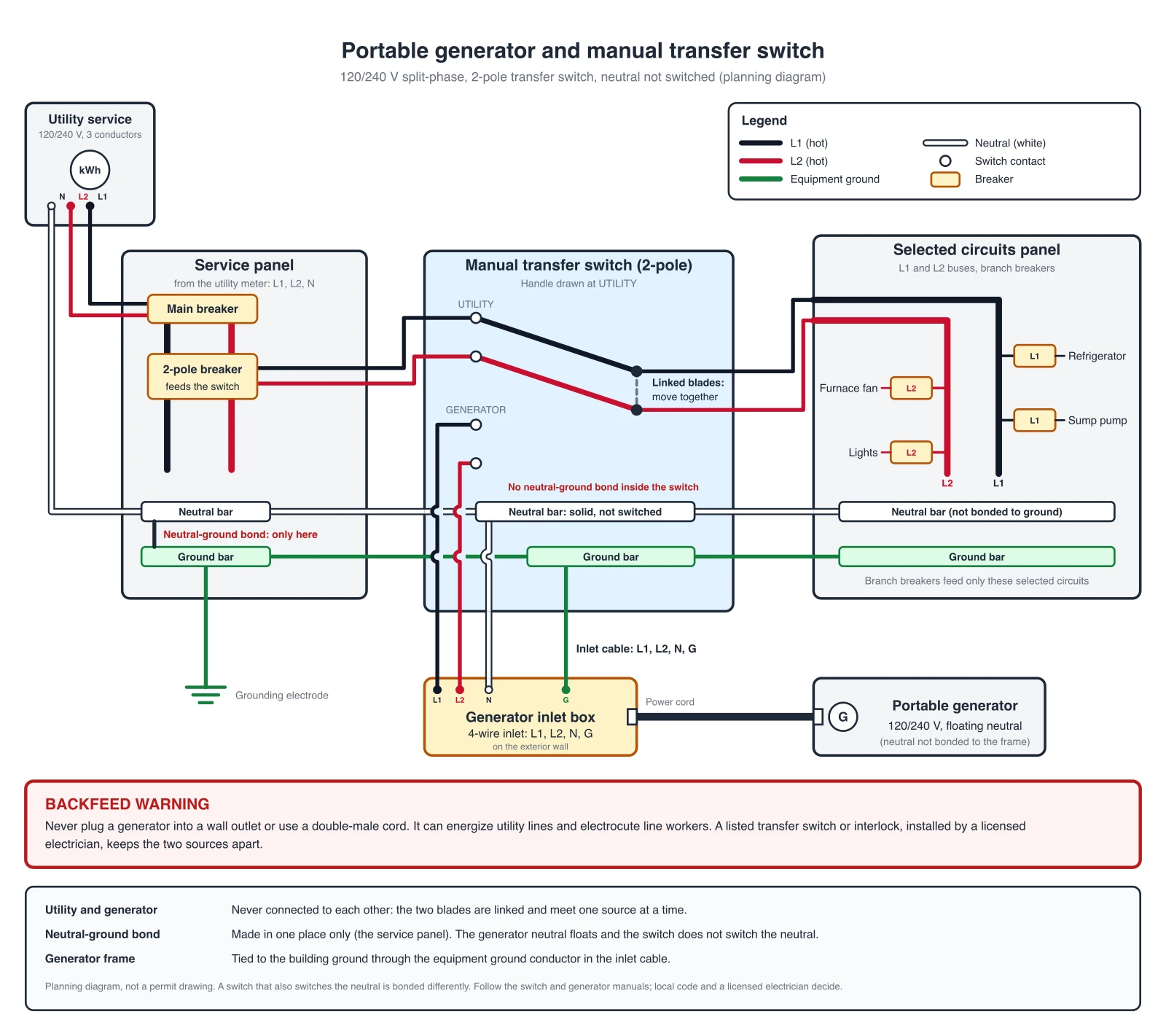
House panel, transfer switch, and generator inlet (exact diagram)
An exact reference diagram, drawn in code from a checked wire list. A 2-pole transfer switch connects the selected-circuits subpanel to the utility or to the generator, never both. The neutral is bonded to ground only at the service panel. From the Generator Transfer Switch Wiring Diagram Generator page.
Three-way switch: one light, two switches (exact diagram)
An exact reference diagram, drawn in code from a checked wire list. Power enters at the first switch, the light is fed after the second, and the two travelers run between the switches in 14/3 cable. The neutral goes straight to the light and never lands on a switch.
12 V automotive relay circuit (exact diagram)
An exact reference diagram, drawn in code from a checked wire list. A small switch current energizes the coil on 86 and 85 and closes the load path from 30 to 87. From the 4-pin and 5-pin relay wiring guide on the blog.
Thermostat wiring for a gas furnace and central AC (exact diagram)
An exact reference diagram, drawn in code from a checked wire list. R and C carry 24 V from the furnace transformer, W calls for heat, Y for cooling, and G for the blower fan. Y and C continue to the condenser contactor coil. For heat pumps (O/B) and heat-only systems, see the Thermostat Wiring Diagram Generator.
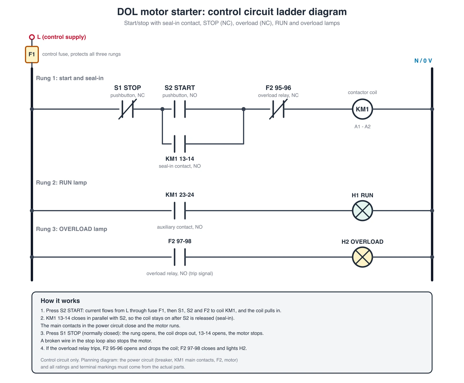
Motor starter control ladder (exact diagram)
An exact reference diagram, drawn in code from a checked wire list. It shows the control circuit only. The power circuit that this coil switches is the next diagram. From the Control Panel Wiring Diagram Generator page.
Three-phase motor starter power circuit (exact diagram)
An exact reference diagram, drawn in code from a checked wire list. The breaker comes first, then the contactor, then the overload relay, then the motor. The KM1 coil and the F2 contact are on the control ladder in this gallery.
For a facility-level view of sources, transformers and feeders, use the Single-Line Diagram Generator. For terminal-level automotive examples, read the 4-pin and 5-pin relay wiring guide before drafting your connections. For the lighting circuit in the gallery, the Three Way Switch Wiring Diagram Generator also has the power-at-the-light layout, the Thermostat Wiring Diagram Generator covers heat-only and heat pump O/B wiring, and the GFCI Outlet Wiring Diagram Generator shows LINE and LOAD wiring. For three or more switch locations, the 4-Way Switch Wiring Diagram Generator adds the 4-way switch between the two 3-way switches. For a single switch controlling one light, use the Light Switch Wiring Diagram Generator, and for a fan with a light kit, the Ceiling Fan Wiring Diagram Generator. For motor and power work, the Three-Phase Motor Wiring Diagram Generator covers 3, 6, 9, and 12 lead connections, and the Solar Panel Wiring Diagram Generator draws series, parallel, and off-grid PV system wiring.
What is a wiring diagram?
A wiring diagram is a drawing that shows the actual electrical connections between the components of a system — which wire runs from which terminal to which terminal. It maps the physical layout: every component, every connection point, and often the wire colors and gauges, so you can build, troubleshoot, or repair the wiring exactly as drawn. Unlike a block sketch, a wiring diagram is meant to be followed wire by wire, which is what this generator draws — labeled components, terminals, and connections on a clean white background.
Wiring diagram vs circuit schematic
A wiring diagram and a circuit schematic describe the same system in two different ways. A schematic is abstract: it uses standardized symbols to show how a circuit works electrically, ignoring where parts physically sit or how wires are routed. A wiring diagram is physical: it shows the real components, their terminals, the wire colors, and the literal connections between them — the picture you use to assemble or trace the wiring. Use a schematic to understand the logic of a circuit, and a wiring diagram to actually wire it. If you need the symbolic, theory-level view instead, our circuit diagram maker focuses on schematic symbols and circuit behavior.
Components and connections a wiring diagram shows
- Components: the power source, switches, outlets, motors, relays, fuses or breakers, lights, transformers, and control devices.
- Terminals: the labeled connection points on each component (for example a thermostat’s R, Y, G, and W terminals, or a motor’s U/V/W).
- Wires: the conductors between terminals, often drawn or labeled with their color (black hot, white neutral, green or bare ground) and gauge.
- Protective devices: fuses, circuit breakers, and overload relays placed in the line they protect.
- Grounds and commons: ground and neutral connections, which keep the system safe and give every device a return path.
Where wiring diagrams are used
Wiring diagrams are the working reference across home electrical, automotive, and appliance projects. In a house, they map the panel, branch circuits, outlets, and switch loops so an installation matches code. In a vehicle, a 12V wiring diagram traces the battery, alternator, starter, fuse box, lights, and grounds — essential when chasing a fault. For appliances and HVAC, they show how a thermostat, transformer, contactor, and motors connect, and on the plant floor a control-panel diagram lays out PLCs, contactors, and motor starters. Anywhere wires connect components, a wiring diagram is how people build and fix it.
How to make a wiring diagram from a description
Describe the system in plain language — the components, the terminals, the wire colors, and how everything connects — and the tool draws a labeled wiring diagram. The more specific you are, the more accurate the result: name the parts ("12V battery, alternator, starter solenoid"), the connections ("ignition switch feeds the starter relay"), and any color or terminal conventions you want shown. Generate a few options, pick the clearest, adjust the description if a connection is wrong, and download the diagram as a PNG for your notes, manual, or build sheet.
Reading and verifying a wiring diagram
To read a wiring diagram, start at the power source and follow each wire to its terminal, checking the color and the component it lands on; trace the return path through neutrals or grounds back to the source. Confirm protective devices sit in the right line and that switches break the intended conductor. AI-generated diagrams are a fast way to draft, study, or document wiring, but treat them as a reference draft rather than a code-compliant plan — for real home or automotive electrical work, always follow your local electrical code and consult a licensed electrician before connecting power.
Exact reference diagrams vs AI drafts
The examples in the gallery are exact reference diagrams. They are drawn in code from a checked wire list, so every wire and label is placed on purpose. We do not show AI-generated wiring images as examples, because image models often draw wrong connections: a cable on the wrong terminal, a fuse in the wrong place, or a neutral tied to ground twice. The generator on this page still produces an AI draft from your prompt. Treat that draft as a rough layout, check every connection against the exact references and the equipment makers’ manuals, and let a licensed electrician decide what gets installed. The gallery covers a house panel with a generator transfer switch, a three-way lighting circuit, a 12 V relay, a thermostat for a furnace and central AC, and both the power circuit and the control circuit of a three-phase motor starter. It does not cover every kind of wiring: heat pumps, star-delta starters, and most other systems are not drawn here. EV chargers and boat 12 V systems have exact diagrams on their own generator pages. No diagram from this page is a permit drawing.
Preguntas frecuentes
Related Engineering Tools
 Engineering
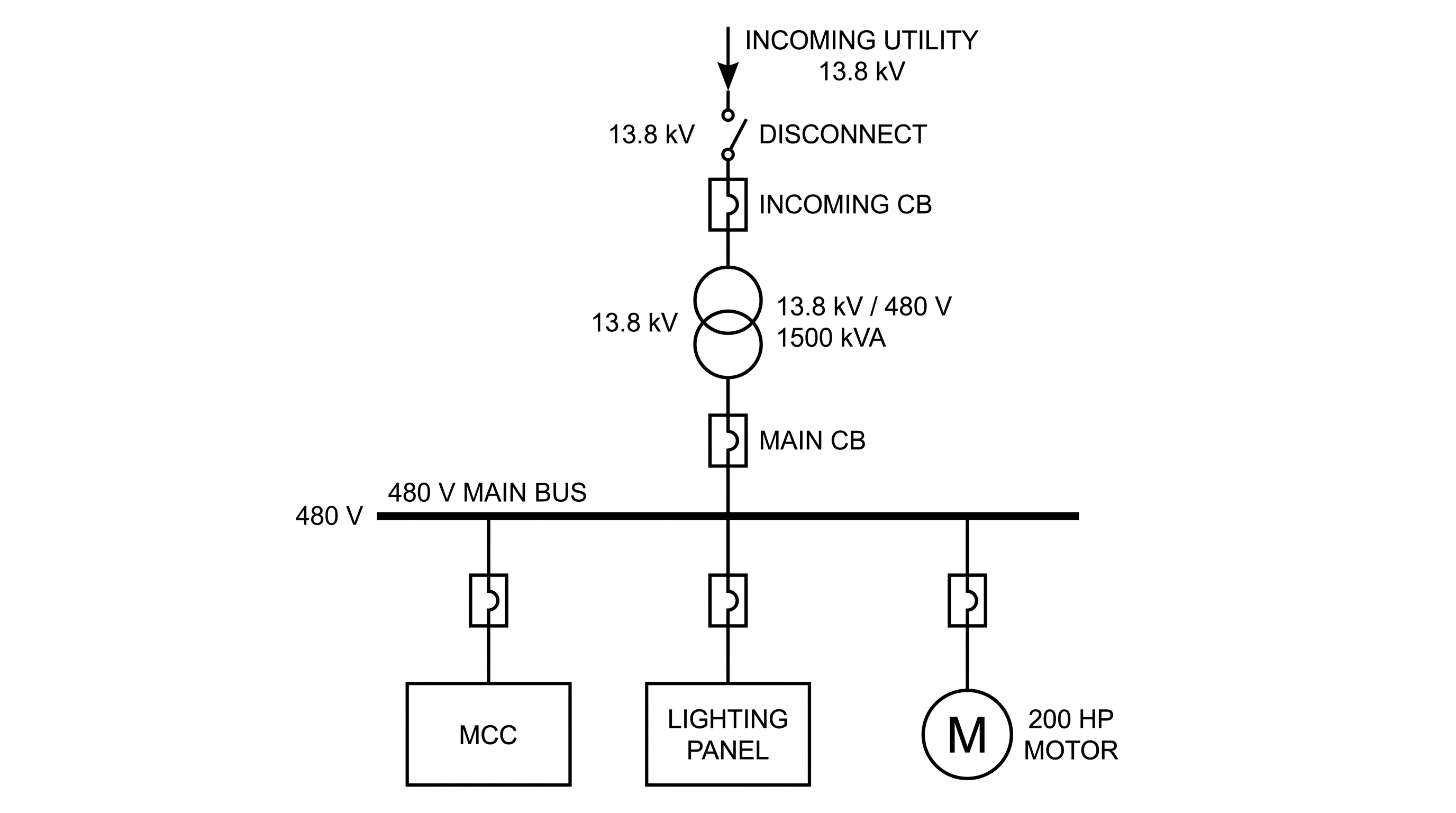
Single-Line Diagram Generator
Power-system one-line diagrams with transformers, buses, and breakers.
 Engineering
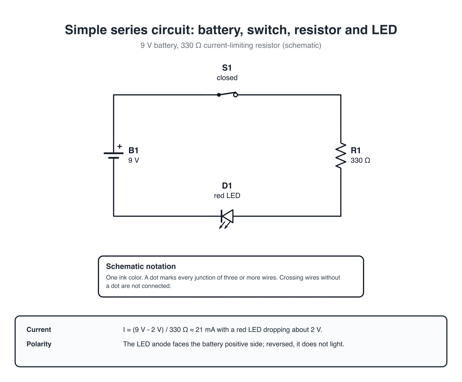
Circuit Diagram Maker
Draw circuit schematics with standard symbols to show how a circuit works electrically.
 Engineering
Schematic Diagram Maker
Create technical schematic diagrams for systems, equipment, and processes.
 Engineering
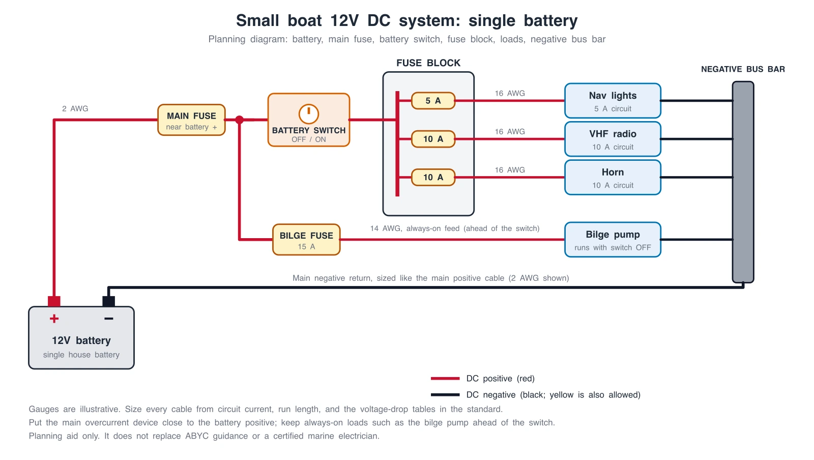
Boat Wiring Diagram Generator
Boat 12V wiring diagrams: single and dual battery, battery switch, fuse block, and bilge pump.
 Engineering
Control Panel Wiring Diagram Generator
Motor starter, PLC input and output, and control panel layout diagrams, with an exact DOL ladder diagram.
 Engineering
EV Charger Wiring Diagram Generator
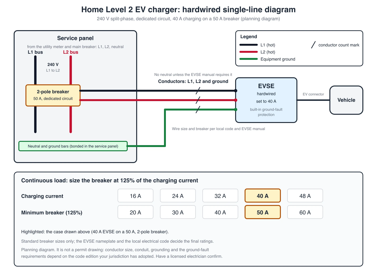
Home Level 2 and NEMA 14-50 outlet diagrams, with an exact hardwired single-line diagram.
 Engineering
Generator Transfer Switch Wiring Diagram Generator
Manual transfer switch, interlock kit, and automatic transfer switch diagrams, with an exact manual transfer switch diagram.
 Engineering
Circuit Symbols Chart
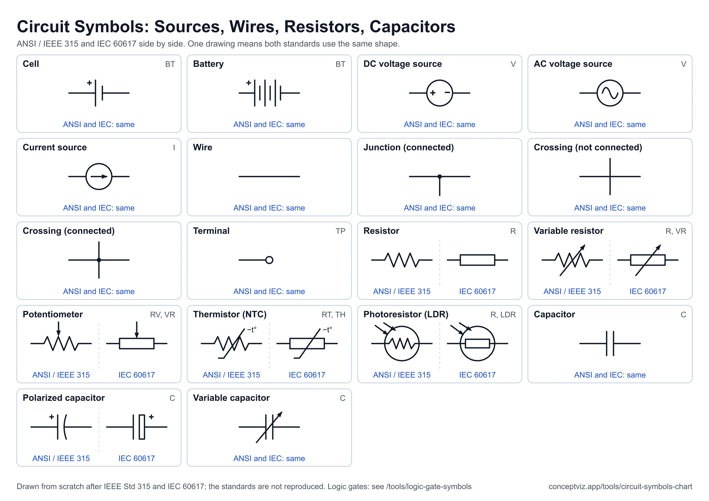
Circuit symbols chart with resistor, capacitor, diode, transistor and more in ANSI and IEC styles, with SVG and PNG downloads and a printable cheat sheet.
 Engineering
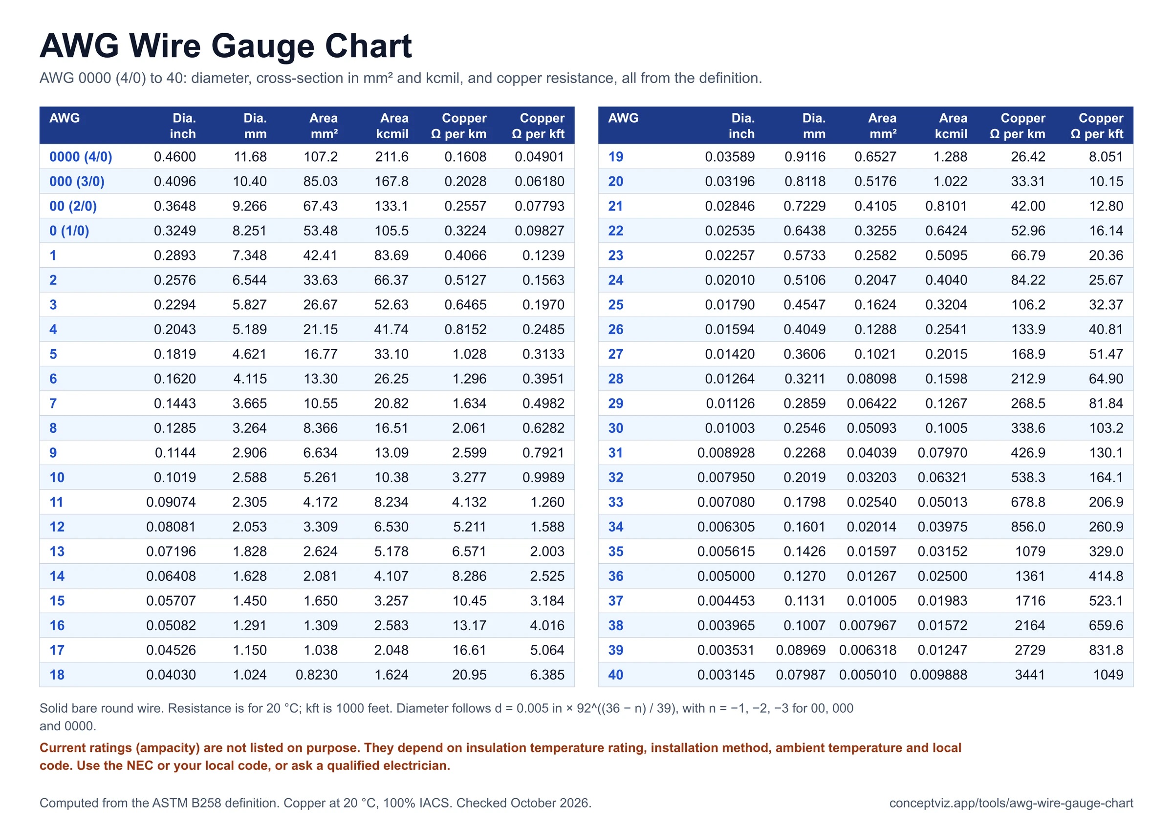
AWG Wire Gauge Chart
AWG 0000 to 40 with diameter, mm², kcmil and copper resistance, plus a voltage drop calculator and printable charts.