Circuit Diagram Maker for Schematics & Circuits
Free online circuit diagram maker. Describe a circuit in plain English — a battery, resistor, capacitor, LED, switch, or a full schematic — and generate a clean, labeled diagram with standard electrical symbols. Built for electronics students, teachers, and hobbyists.
Generate circuit diagrams from text
Create a clean circuit diagram reference for learning, documentation, and early planning.
Best for educational schematics, wiring layouts, logic diagrams, panel drafts, and presentation-ready circuit references.
Example prompts
More examples
Reference image only. Verify electrical logic, ratings, safety, tolerances, and local rules before building hardware.
Circuit diagram preview
Generated image output appears here.
Circuit diagram preview
A clean generated circuit reference image will appear here.
Circuit Diagram Examples
Schematics covering series, parallel, RC, transistor, logic, and bridge circuits
Simple DC Series Circuit
A single-loop series circuit: battery, switch, resistor, and LED on one path, with current flowing the same through every component.
Series & Parallel Resistors
Resistors branch in parallel and chain in series — the layout you reach for when solving for total resistance.
RC Charging Circuit
A resistor and capacitor with a voltage source — the classic timing circuit governed by the time constant τ = RC.
Transistor Amplifier
A common-emitter BJT amplifier with bias resistors and coupling capacitors — a core building block of analog electronics.
Digital Logic Gates
AND, OR, NOT, and NAND gates wired into combinational logic — drawn with standard gate symbols for digital design.
Wheatstone Bridge
Four resistors in a diamond with a galvanometer across the bridge — the standard layout for precise resistance measurement.
What is a circuit diagram?
A circuit diagram — also called a schematic — is a drawing that shows how the parts of an electrical circuit connect, using standard symbols instead of pictures of the real parts. Each component (a resistor, a capacitor, a battery) has its own symbol, and the lines between symbols represent the wires that carry current. Because a schematic shows the electrical connections rather than the physical layout, it stays the same whether the real circuit is built on a breadboard, a printed circuit board, or a tangle of jumper wires. This maker turns a plain-English description into that kind of clean, labeled schematic for you.
Common circuit symbols and what they mean
- Resistor: a zig-zag line (US) or a rectangle (IEC) that limits current; labeled with a value in ohms (Ω).
- Capacitor: two parallel lines that store charge; one curved line marks a polarized (electrolytic) capacitor, rated in farads (F).
- Battery / source: short and long lines stacked together for a battery, or a circle for a generic voltage or current source.
- Switch: a break in the line with a hinged lever that opens or closes the circuit.
- LED: a diode triangle pointing to a bar, with two small arrows showing it emits light.
- Ground: a set of stacked horizontal lines marking the 0V reference point that connections return to.
Series versus parallel circuits
How components are wired changes how a circuit behaves. In a series circuit the parts sit on a single loop, so the same current flows through each one and the voltage divides between them — which is why one broken bulb in a series string takes the rest down with it. In a parallel circuit the parts sit on separate branches across the same two points, so each branch gets the full voltage and the current splits between them. Most real designs mix the two: a parallel block of resistors might sit in series with another part, exactly like the series-parallel example in the gallery above.
Schematic vs pictorial and wiring diagrams
A schematic uses abstract symbols and is the best way to understand how a circuit works electrically. A pictorial diagram draws components as they actually look — handy for beginners following along on a breadboard. A wiring diagram shows the physical routing of real wires and connectors, which is what you want when installing or servicing equipment. For power and electrical work there is also the single line diagram (one-line diagram), which collapses a three-phase system into a single line so a whole panel, feeder, or distribution layout fits on one readable page. Decide which view you need before you describe your circuit.
How to describe a circuit to generate one
- Name the source first: state the supply, such as "a 9V battery" or "a 5V DC source".
- List the components with values: for example "a 330 ohm resistor and a red LED".
- Say how they connect: use "in series", "in parallel", or "branching from" so the topology is unambiguous.
- Add the extras you want labeled: a switch, a ground symbol, current-flow arrows, or node labels.
- Keep it to one clear sentence per idea — "a 9V battery in series with a switch, a 330Ω resistor, and an LED" generates a far cleaner schematic than a vague request.
Who uses an online circuit diagram maker
Students use it to draw the circuits in a physics or electronics assignment without wrestling with desktop CAD. Teachers generate clear, labeled diagrams for worksheets, slides, and exam questions in seconds. Hobbyists and makers sketch a circuit before they build it on a breadboard, document a finished project, or share a design with others. Because everything runs in the browser and is free to start, it suits quick reference diagrams, homework, and concept sketches — for production hardware or safety-critical wiring, always have the result reviewed against a verified design.
Frequently Asked Questions
Related Diagram Tools
 Physics
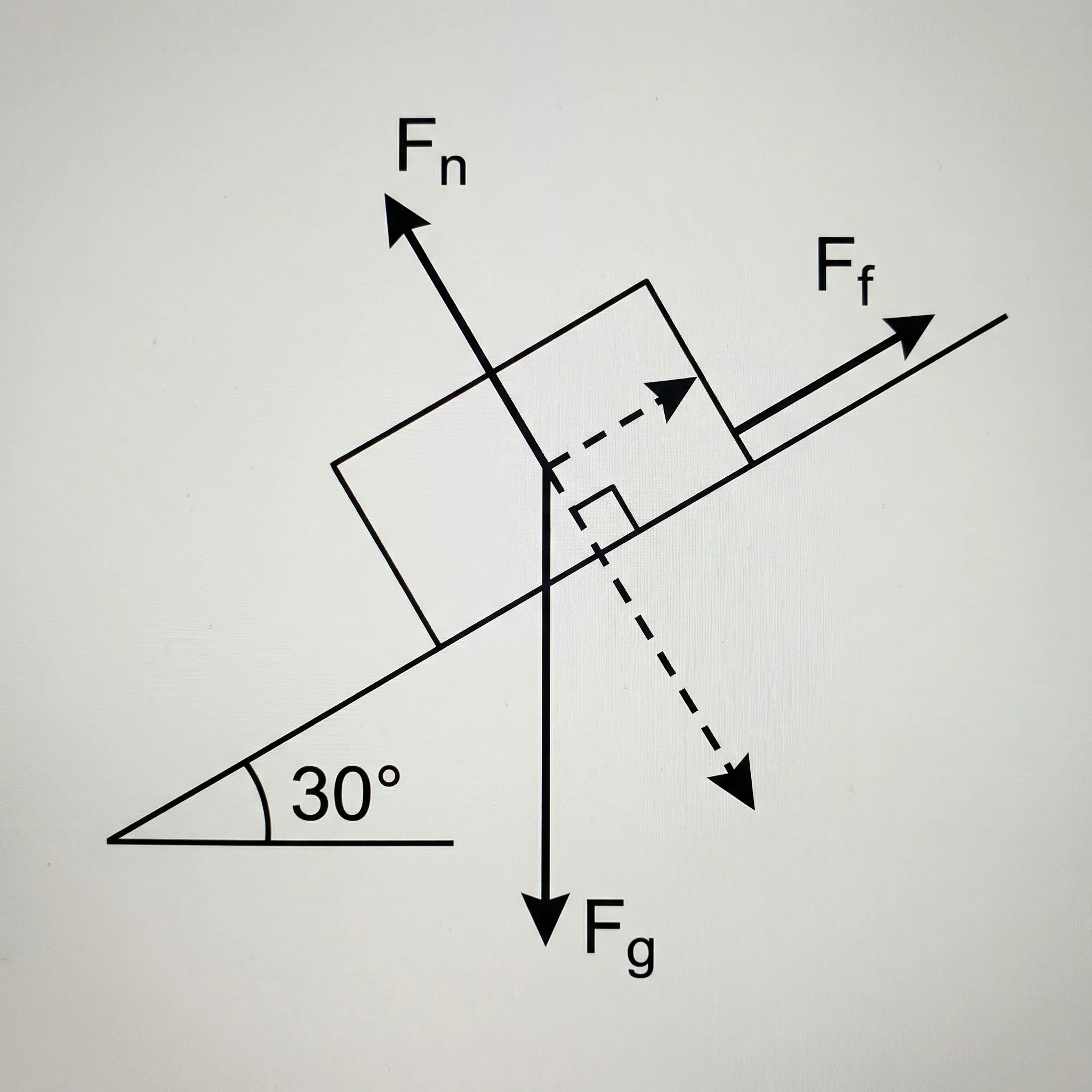
Free Body Diagram Generator
Draw labeled free body diagrams with force vectors for physics problems.
 Visualization
Text to Diagram Generator
Turn a written description into a clean diagram, flowchart, or architecture map.
 Science
AI Scientific Image Generator
Generate clear, labeled scientific figures and experiment setups from a prompt.