Thermostat Wiring Diagram Generator R, C, W, Y, G and O/B
Exact thermostat wiring diagrams: heat-only 2 wire, furnace and AC 5 wire with C wire, and heat pump O/B. Terminal table and an AI generator.
Thermostat Wiring Diagrams by System Type
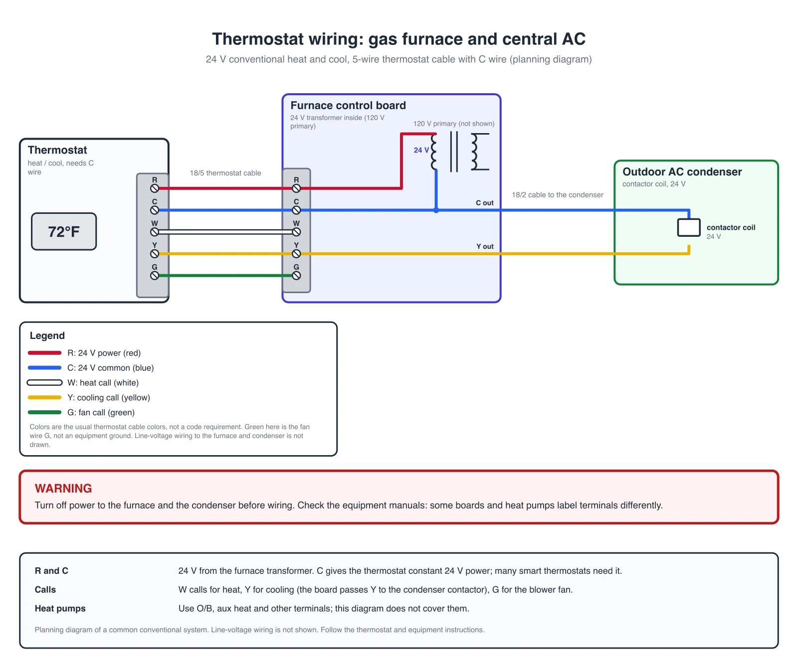
Exact diagrams drawn in code from a reviewed list of connections. Each shows the thermostat terminals, the control board with its 24 V transformer and, where there is one, the outdoor unit. Open an image for the full-size version.
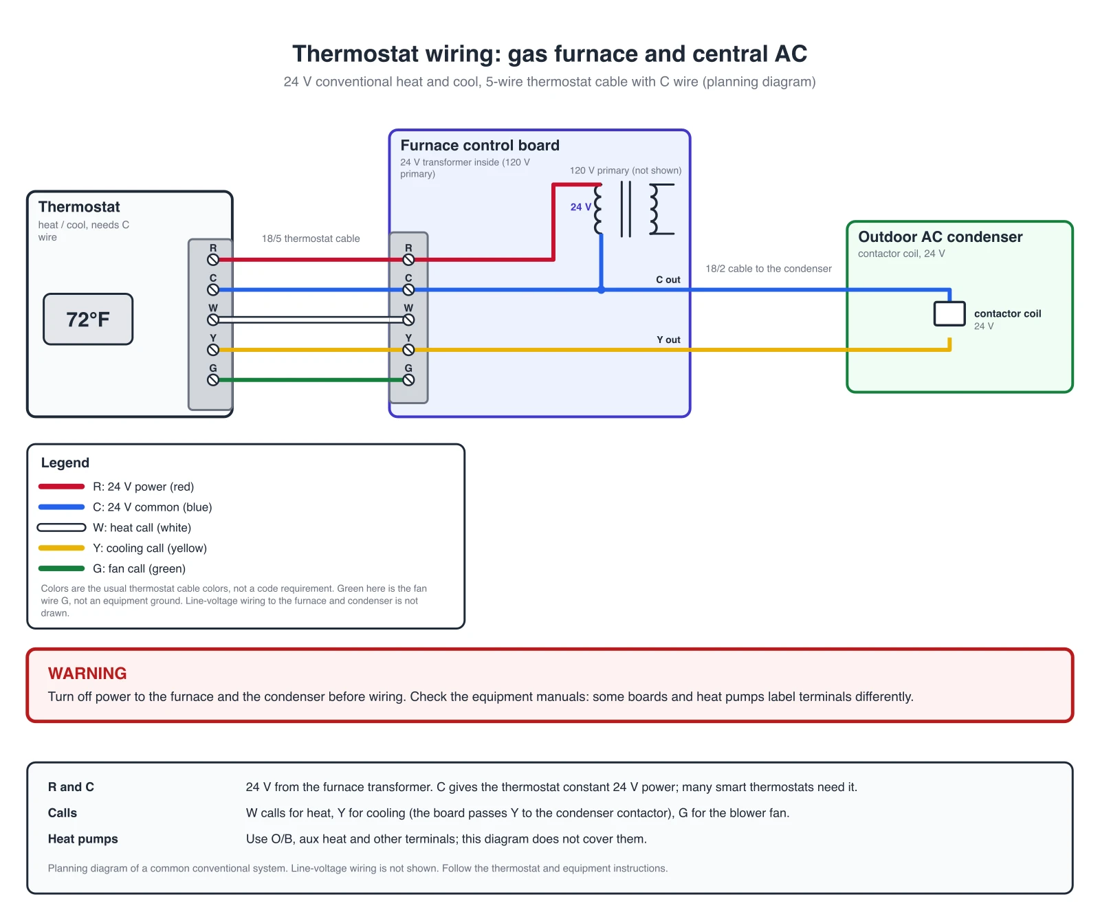
Furnace and AC, 5 wires (R, C, W, Y, G)
The usual one-transformer heat and cool system. R carries 24 V from the furnace transformer, C is the common, W calls for heat, Y calls for cooling and G runs the blower fan. The control board passes Y and C on to the contactor coil of the outdoor condenser.
Checked against the reference table: conventional furnace and AC, 5 wires (R C W Y G).
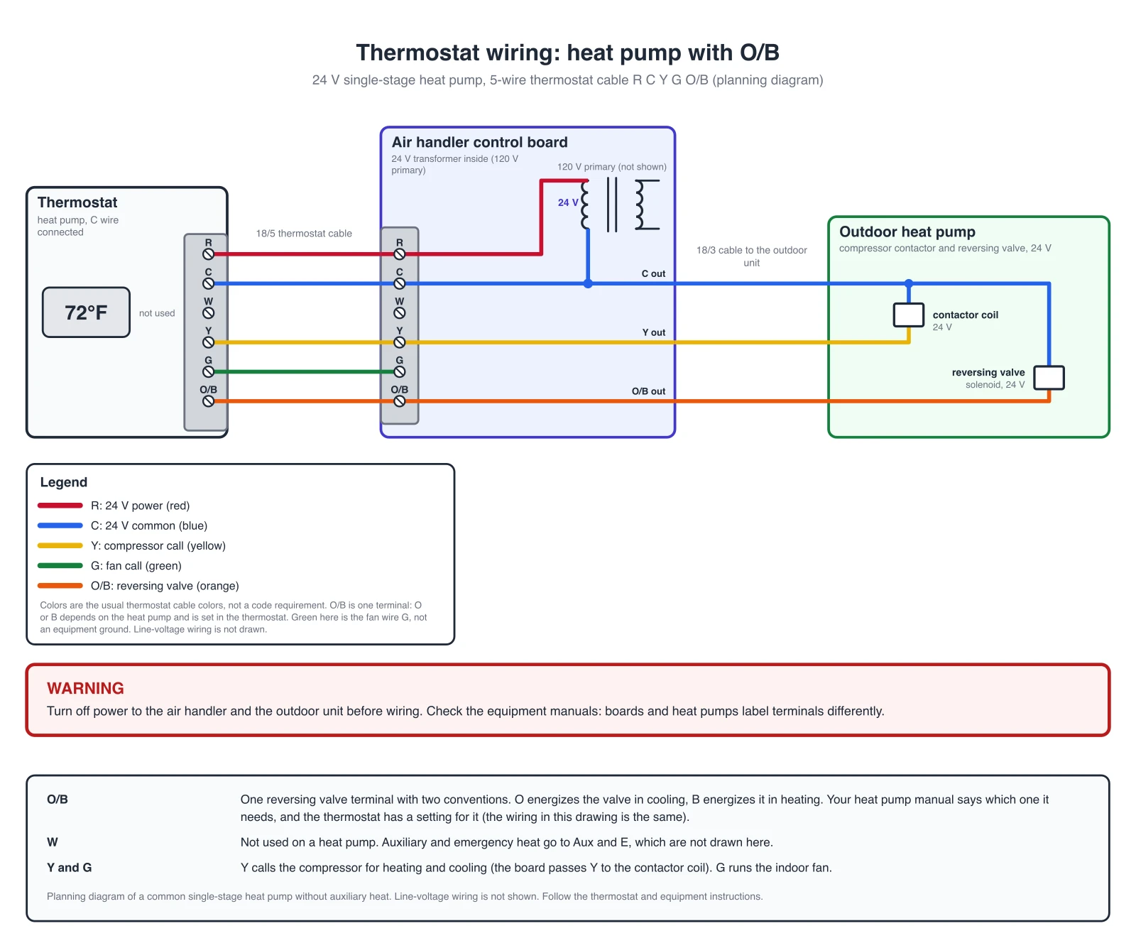
Heat pump, 5 wires (R, C, Y, G, O/B)
A heat pump has no separate heat call. Y calls the compressor for both heating and cooling, and the O/B terminal drives the reversing valve that decides which way the heat moves. W is left empty. Auxiliary and emergency heat go to Aux and E, which this drawing does not show. If your old thermostat also had a wire on Aux, E or L, connect it to the terminal with the same letter, as your thermostat manual says.
Checked against the reference table: single-stage heat pump, 5 wires (R C Y G O/B).
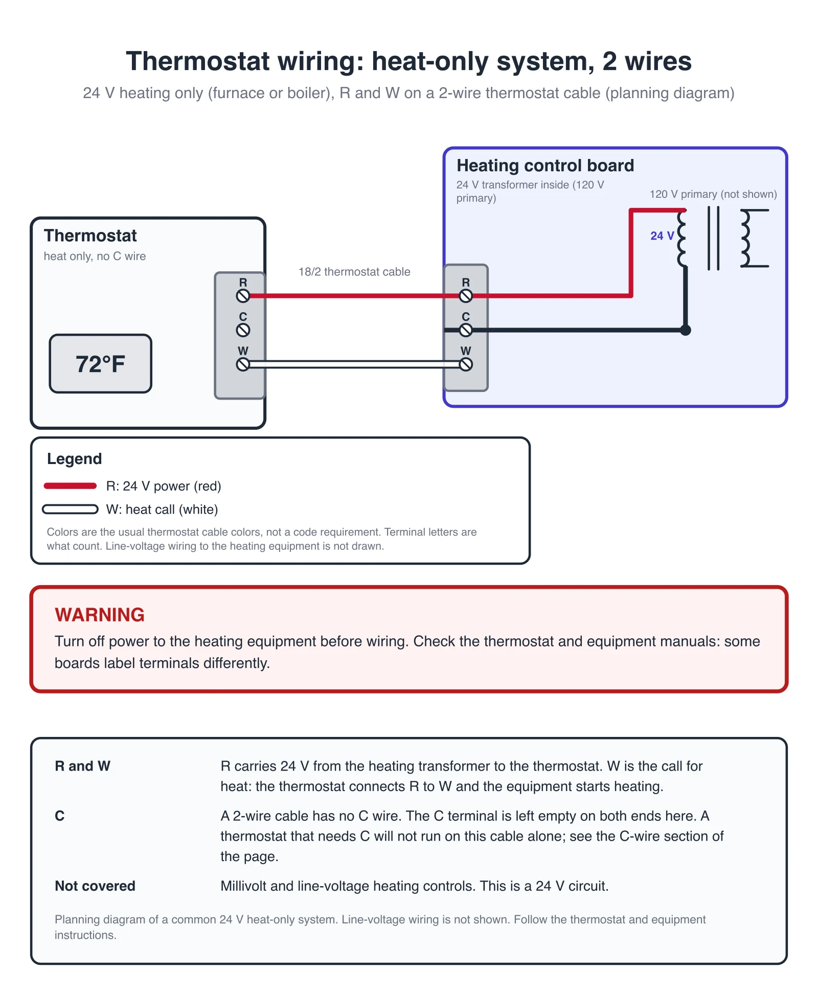
Heat only, 2 wires (R and W)
A furnace or boiler with no cooling. R carries 24 V to the thermostat and W is the call for heat. A 2-wire cable has no C wire, so the C terminal stays empty on both ends.
Checked against the reference table: heat-only system, 2 wires (R and W).
Thermostat Terminals: What R, C, W, Y, G and O/B Mean
The meaning of each letter as the thermostat makers define it (see the sources below). Terminal names differ a little between makers, so match your thermostat manual.
| Terminal | Meaning | Note |
|---|---|---|
| R | 24 VAC power from the heating transformer | The power side of the 24 V circuit. Some makers label it Rh. |
| Rc | 24 VAC power from the cooling transformer | With one transformer there is one red wire and the thermostat joins R and Rc (a slider tab or a jumper). With two transformers there are two red wires and the joint is removed. |
| C | 24 VAC common | The return side of the 24 V circuit. On a two-transformer system the common comes from the cooling transformer. |
| W | Heat, stage 1 | Not used on a heat pump. Honeywell marks W "do not use this terminal for heat pump applications". |
| Y | Compressor contactor (cooling call on a conventional system) | On a heat pump the same terminal calls the compressor for heating and cooling. |
| G | Fan | Runs the indoor blower. Not an equipment ground. |
| O/B | Changeover (reversing) valve, heat pump only | O is energized in cooling, B is energized in heating. The heat pump manual says which one it needs. |
| Aux, E | Auxiliary heat, emergency heat | Heat pump backup heat. Not drawn on this page. |
Usual Thermostat Wire Colors
Usual colors, not a rule. The terminal letter is what counts, so label each wire before you disconnect it.
| Usual wire color | Terminal |
|---|---|
| Red | R (Rc, Rh) |
| Blue | C |
| White | W |
| Yellow | Y |
| Green | G |
| Orange | O/B |
This page covers the 24 V thermostat wiring only. For the refrigerant cycle, ducts and airflow of the same equipment, see the HVAC Diagram Generator. For other wiring, such as home, automotive, or appliance systems, use the Wiring Diagram Maker.
AI illustration of your thermostat wiring
Describe a system to get a quick picture. AI images can draw wrong connections, so use the exact diagrams and the table above for the real connections and check every terminal of an AI picture. You can also use the generator below to make an illustration of your own setup.
Generate an AI Thermostat Wiring Illustration
Example: Exact reference for this connection (drawn in code, not the AI output)View full sizePreview is free on this page ·
Your thermostat wiring diagram will appear here
AI diagrams are drafts. Check every terminal letter and wire against your equipment manual.
Sources (checked October 2026):
- Honeywell Home T6 Pro programmable thermostat installation instructions (Resideo, form 33-00181EFS-13): terminal designations, heat-only, conventional and heat pump wiring, O/B setting, C-wire adapter
- White-Rodgers (Emerson) 1F89-211 heat pump thermostat installation and operation instructions, part 37-6233G: O/B switch, wiring diagrams, precautions
- Honeywell Home support, "How do I wire my thermostat?"
Wire colors are the usual convention and are not a code requirement.
What a thermostat wiring diagram shows
A thermostat wiring diagram shows which wire from the thermostat goes to which terminal on the heating and cooling equipment. Residential thermostats work on 24 V. A transformer in the furnace or air handler supplies the 24 V, and the thermostat closes small circuits between the terminals to call for heat, cooling or the fan. Each terminal has a letter, such as R, C, W, Y, G or O/B, and the letter tells you what that wire does. This page draws three common systems as exact diagrams and lists what each letter means. It covers the 24 V control wiring only, not the line-voltage wiring of the furnace, the air handler or the outdoor unit.
How to tell which diagram is yours
- Start with the equipment, not the number of wires. A furnace or boiler with no cooling is heat only. A furnace or air handler with an outdoor air conditioner is a conventional heat and cool system. An outdoor unit that both heats and cools is a heat pump, and its thermostat has an O/B terminal for the reversing valve.
- The wires on the old thermostat give a hint. Heat only usually has R and W. A conventional system adds Y and G, and often C. A heat pump has O or B in place of W. But wire counts and colors vary between installations, so read the letters on the old thermostat terminals and on the control board, and label every wire with its terminal letter before you disconnect it. The White-Rodgers instructions tell installers to identify each wire on the old thermostat before removing it.
- A system can also have two transformers, extra stages, a humidifier or a zone panel. Those are outside this page. If the equipment manual shows more terminals than the diagram here, follow the manual.
The C wire: what it is and what to do without one
- C is the 24 V common. R is the 24 V power from the transformer, and C is the other side of the same transformer winding, so R and C together give the thermostat a constant 24 V supply. Without C, the thermostat has to get its power another way, such as batteries.
- Whether a thermostat needs C depends on the model. The Honeywell T6 Pro manual says its C terminal is optional if batteries are installed, but recommended. Other models require it. Read the manual of your thermostat, and do not assume.
- The most common replacement case is a cable with four wires, R, W, Y and G, and no C. There are three ways to deal with it, and your thermostat manual says which it allows. One is a spare conductor, if the cable has one, connected to C at both the thermostat and the equipment. Another is a thermostat that runs on batteries: the Honeywell T6 Pro manual lists C as optional when batteries are installed. The third is a C-wire adapter. The Honeywell T6 Pro manual names the THP9045A1098 adapter for heat and cool systems that have only four wires at the thermostat. It uses the K terminal in place of Y and G, so that one wire controls both the fan and the compressor, and the unused wire becomes the common wire. Follow the adapter instructions.
- Two things to avoid. Do not join C to R: that shorts the transformer, and the White-Rodgers instructions warn that a short or incorrect wiring will damage the thermostat. And on a system with two transformers, the common must come from the cooling transformer, as the Honeywell manual says.
O or B: which reversing valve terminal
- A heat pump has one reversing valve that switches the outdoor coil between heating and cooling. The thermostat drives it from one terminal, O/B. There are two conventions. With O, the valve is energized in cooling. With B, the valve is energized in heating. The White-Rodgers 1F89 sheet describes exactly this, and the Honeywell T6 Pro has an installer setting "Reversing Valve O/B" with the options O (O/B in cool) and B (O/B in heat).
- The wire is the same in both cases: it runs from the O/B terminal to the reversing valve circuit of the heat pump. What changes is the thermostat setting. The White-Rodgers 1F89 ships set to O because that fits the majority of heat pump applications, but some heat pumps need B. Do not pick by brand name or wire color. Look in the manual of the heat pump or the air handler, or at the old thermostat setting, and set the new thermostat to match.
- If the setting is wrong, the heat pump runs backwards: it cools when you call for heat. After wiring, run a short heat call and a short cool call and check that the air matches. If it does not, fix the O/B setting before you touch any wire.
Wire colors
The diagrams use the colors installers usually see: red for R, blue for C, white for W, yellow for Y, green for G and orange for O/B. These colors are a habit, not a rule. Old installations, repairs and splices can break them. The terminal letter is what counts, so trust the letter on the old thermostat or on the control board, label wires before you disconnect them, and take a photo of the old wiring. The green wire on a thermostat cable is the fan wire G, not an equipment ground. On the red wires: with one transformer there is one red wire, and the thermostat joins R and Rc with a slider tab or a jumper. With two transformers there are two red wires, one on R and one on Rc, and the joint is removed.
Before you wire the thermostat
- Turn off the power to the furnace or air handler and to the outdoor unit before you touch a wire. The installation instructions of the thermostat makers say to switch off the electricity at the main fuse or circuit breaker box until the installation is complete.
- Use a low-voltage thermostat only on a low-voltage system. Do not use these diagrams for millivolt or line-voltage thermostats. The White-Rodgers instructions say not to use their thermostat with line-voltage or millivolt systems.
- Do not short terminals on the gas valve or the primary control to test. Wire by terminal letter, set the thermostat to the right system type, then restore power and check heat, cool and fan one at a time. A diagram from this page is a planning picture. It does not replace the thermostat and equipment instructions or the electrical code that applies in your area, and a licensed electrician or HVAC technician decides what gets installed.
Exact diagrams vs AI drafts
The three diagrams above are exact reference diagrams. They are drawn in code from a reviewed list of connections, and a checker compares every drawing with a reference table of the thermostat connections, so each terminal letter goes to the terminal with the same letter and a heat pump has no W wire. We do not show AI-generated wiring images as examples, because image models can draw wrong connections, for example Y on the fan terminal, R joined to C, or a W wire on a heat pump. The generator on this page still produces an AI illustration from your prompt. Treat it as a rough picture, compare it with the exact diagrams and with the equipment manual, and let a qualified person decide what gets installed.
Frequently Asked Questions
Related Engineering Tools
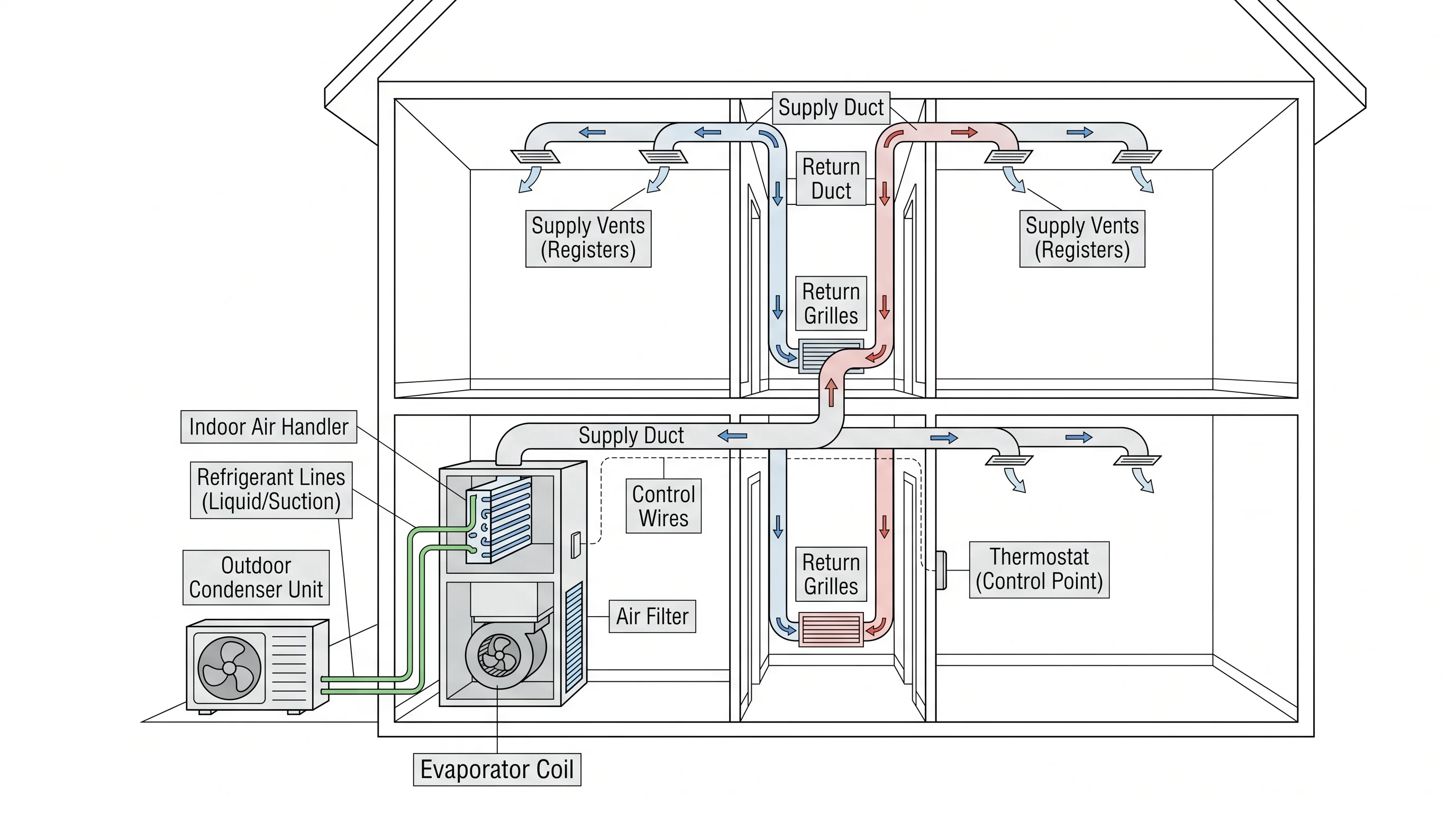 Engineering
HVAC Diagram Generator
Split systems, heat pump refrigerant cycles, airflow and chiller plants as system diagrams.
 Physics
Wiring Diagram Maker
Wiring diagrams for home, automotive, appliance, and industrial systems from a plain-English description.
 Engineering
Control Panel Wiring Diagram Generator
Direct-on-line motor starter power circuit and start/stop ladder diagram, PLC I/O and panel layouts.
 Engineering
Generator Transfer Switch Wiring Diagram Builder
Manual switch, interlock kit and ATS hookups with exact reference diagrams.