Circuit Symbols Chart ANSI and IEC Side by Side
Circuit symbols chart with resistor, capacitor, diode, transistor and more in ANSI vs IEC styles. Search, download SVG or PNG, print a cheat sheet.
Standard
62 symbols shown. Click any symbol to enlarge it and download SVG or PNG.
Power and sources
Wires and connections
Resistors
Capacitors
Inductors and transformers
Diodes and thyristors
Transistors
Switches and relays
Meters
Ground
Fuse, lamp and sound
Motors and generators
Amplifier, antenna, crystal
Logic gates (AND, OR, NOT, NAND, NOR, XOR) have their own chart with truth tables. Open the logic gate symbols chart
Printable circuit symbols cheat sheet
Four landscape sheets cover every symbol, plus a fifth sheet with only the symbols that look different in ANSI and IEC. Pick A4 or US Letter, color or black and white, then download or print.
Sheet
Paper (landscape)
Printing
Scroll sideways on small screens. PNG downloads are about 300 dpi for the chosen paper.
Free Circuit Symbols Chart Sheets
Every sheet below is drawn from the same symbols as the tool above. View, download and print them free, no sign-up.
Circuit Symbols Chart: Sources, Resistors, Capacitors
Power sources, wires, resistors and capacitors, with the ANSI zigzag and IEC rectangle resistor side by side.
Reference sheets
Study aids
Printer friendly
ANSI vs IEC: why the same part has two drawings
- There are two main families of circuit symbols. ANSI / IEEE Std 315 (also known as ANSI Y32.2) is used in the United States and by most US textbooks, data sheets and simulators. IEC 60617 is the international standard used across Europe and in many other countries. This chart draws 62 common symbols and shows both styles next to each other wherever they differ.
- Most symbols are identical in both standards: the diode triangle, the capacitor plates, the inductor loops, the transistors, the switch blade, the meters, the ground symbols and the motor circle. The differences cluster in a few places. A resistor is a zigzag in ANSI and a plain rectangle in IEC. A polarized capacitor uses a curved plate in ANSI and a hollow box in IEC. A transformer is two coils with core lines in ANSI and two overlapping circles in IEC. A relay coil is a circle in ANSI and a rectangle in IEC, a fuse is an S-curve in ANSI and a rectangle with a line in IEC, and an op-amp is a triangle in ANSI and a rectangle with an amplifier mark in IEC.
How to read the symbols
Every symbol has terminals, the ends of the leads, and some have polarity or direction that matters. A diode conducts from the anode, the flat side of the triangle, toward the bar, which is the cathode. The long plate of a cell or battery is the positive side. On a bipolar transistor the arrow is on the emitter: it points out of the symbol for an NPN part and in toward the base for a PNP part. On a MOSFET the arrow on the body lead points toward the channel for an N-channel device and away from it for a P-channel device, and a broken channel line means an enhancement type. On a JFET the gate arrow points into the channel for N-channel. A dot where two wires meet means they are connected, and wires that cross with no dot are not.
Reference designators: R, C, L, D, Q and the rest
Next to each symbol on a schematic you will see a letter and a number, such as R1, C3 or Q2. The letter is the reference designator and tells the reader what kind of part it is: R for resistors, C for capacitors, L for inductors, D for diodes and LEDs, Q for transistors and thyristors, U or IC for integrated circuits, S or SW for switches, K for relays, F for fuses and M for motors. Each card on this page lists the usual letters, and you can type a letter into the search box to find every symbol that uses it.
Which style should you use?
Use the style your teacher, employer or client expects, and keep it the same across the whole drawing. US courses and most hobby schematics use the ANSI zigzag resistor. Drawings for European customers, and school courses in the UK and much of Europe, use the IEC rectangle. Mixing the two in one diagram works for people who know both, but it is easy to misread. For wiring diagrams in the field, follow the standard named in the job specification.
Sources and what this chart does not cover
All symbols are drawn from scratch for this page. They follow the shapes in IEEE Std 315 and IEC 60617 as shown in public teaching material, and the standards themselves are not reproduced. The IEC database is paid and the drawings here are not a substitute for it: for a controlled drawing, check the current edition of the standard. Where a standard has no drawing that we could verify from public sources, such as an IEC signal ground, the page shows the other style only and says so. Logic gates are not repeated here and have their own chart. Three-phase power, one-line diagrams and installation symbols for building wiring are outside the scope of this chart.
Frequently Asked Questions
Related Electronics Tools
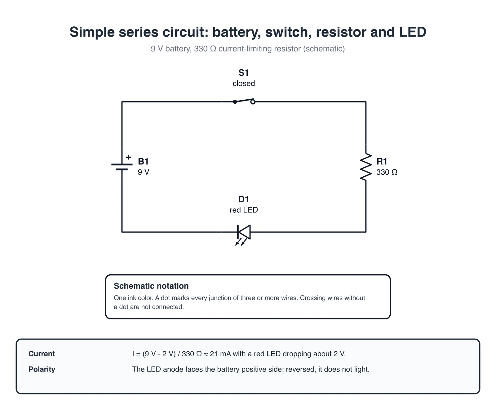 Electronics
Circuit Diagram Maker
Draw circuit diagrams with standard symbols for physics and electrical engineering.
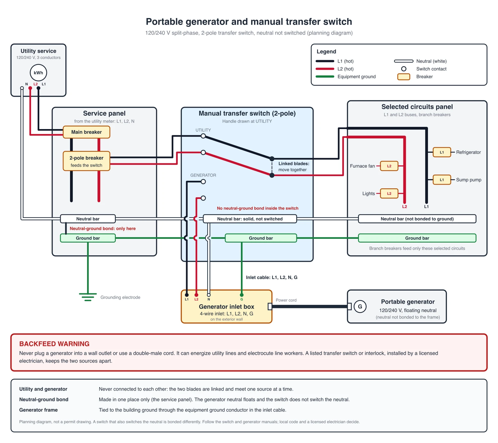 Electrical
Wiring Diagram Maker
Generate labeled wiring diagrams and electrical schematics online.
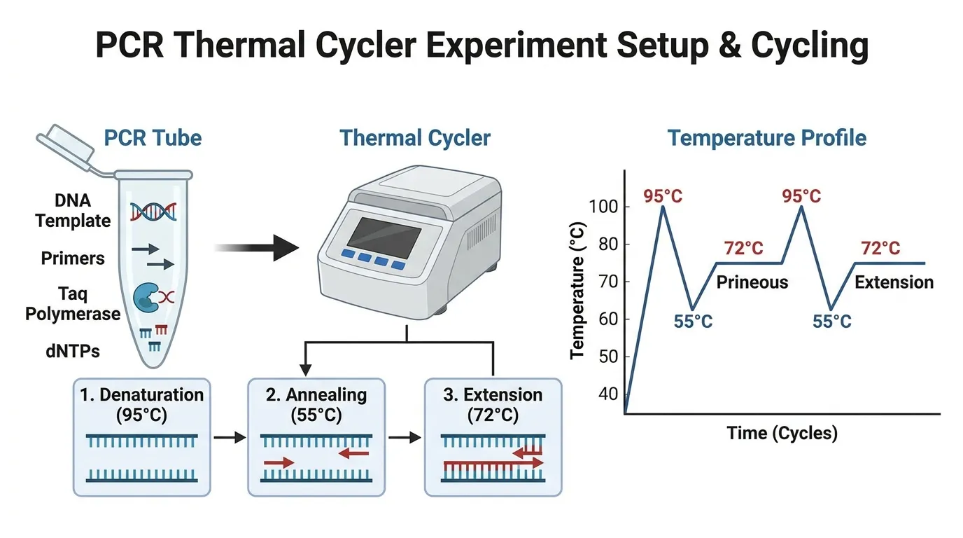 Research
Schematic Diagram Maker
Generate schematic diagrams for lab equipment and experimental apparatus.
 Electronics
Logic Gate Symbols
AND, OR, NOT, NAND, NOR and XOR in ANSI and IEC symbols with computed truth tables.
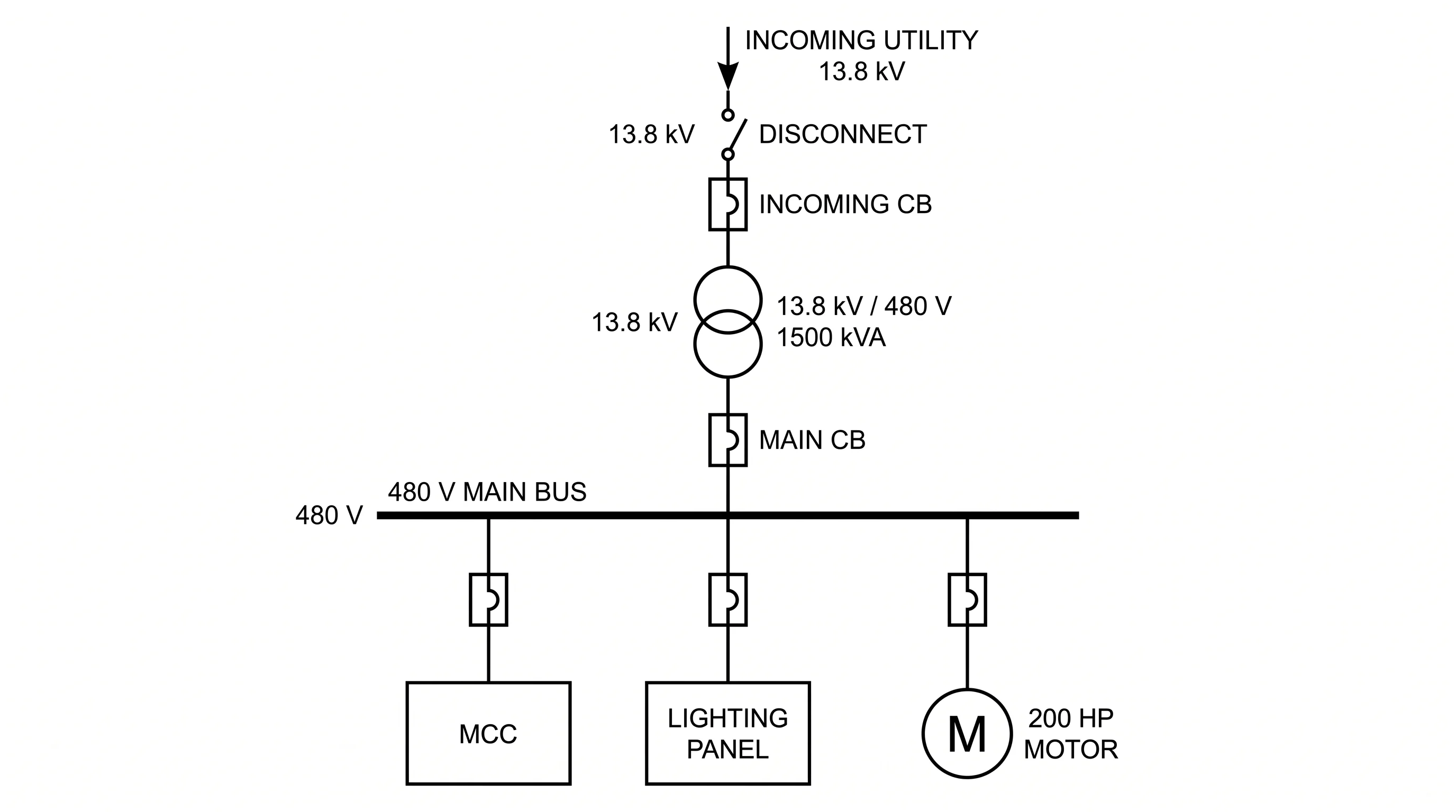 Engineering
Single-Line Diagram Generator
Create electrical single-line diagrams showing utility, transformers, buses and loads.
 Engineering
Block Diagram Generator
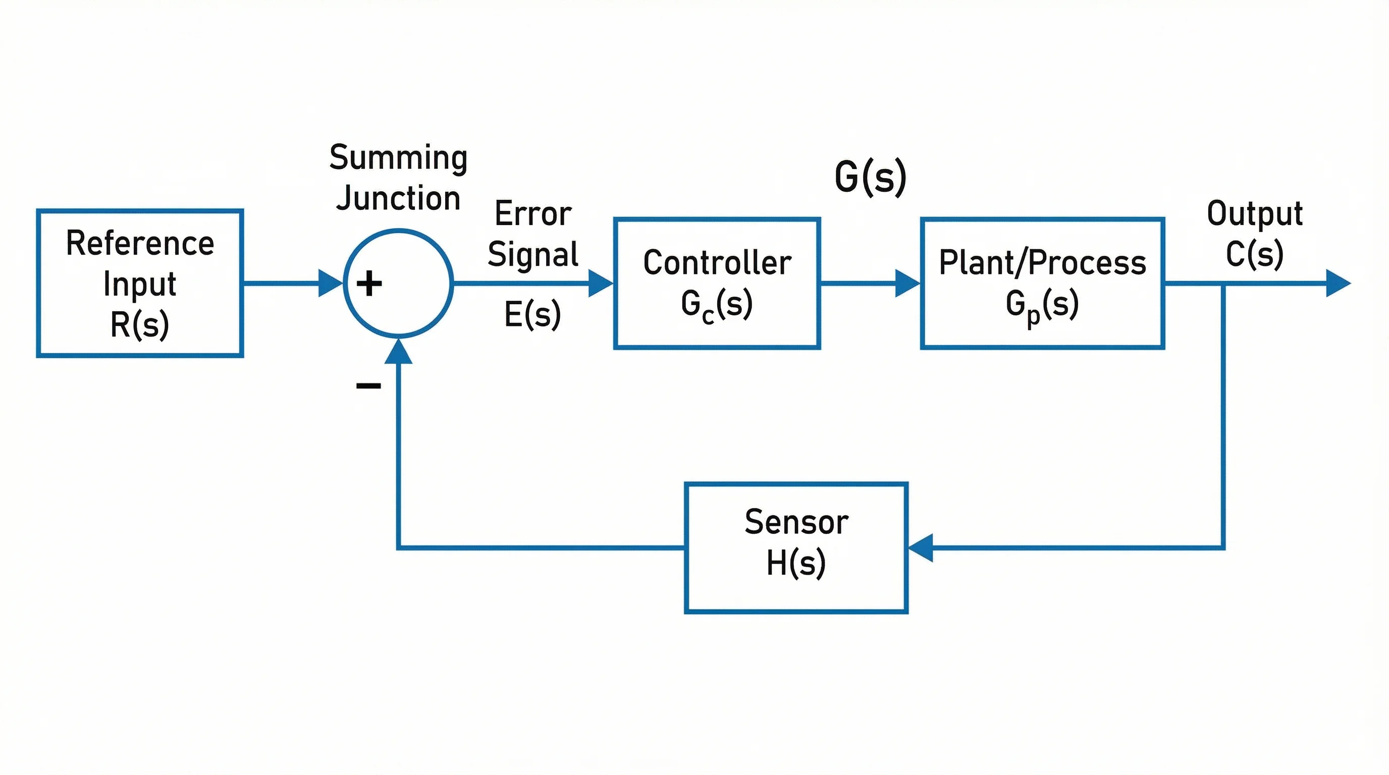
Create block diagrams for control systems, signal paths and system architecture.