Generator Transfer Switch Wiring Diagram Generator for Manual, Interlock and ATS Setups
Generate a generator transfer switch wiring diagram from text: manual switch with inlet box, interlock kit, or ATS. With exact reference diagrams.
Create Your Transfer Switch Wiring Diagram
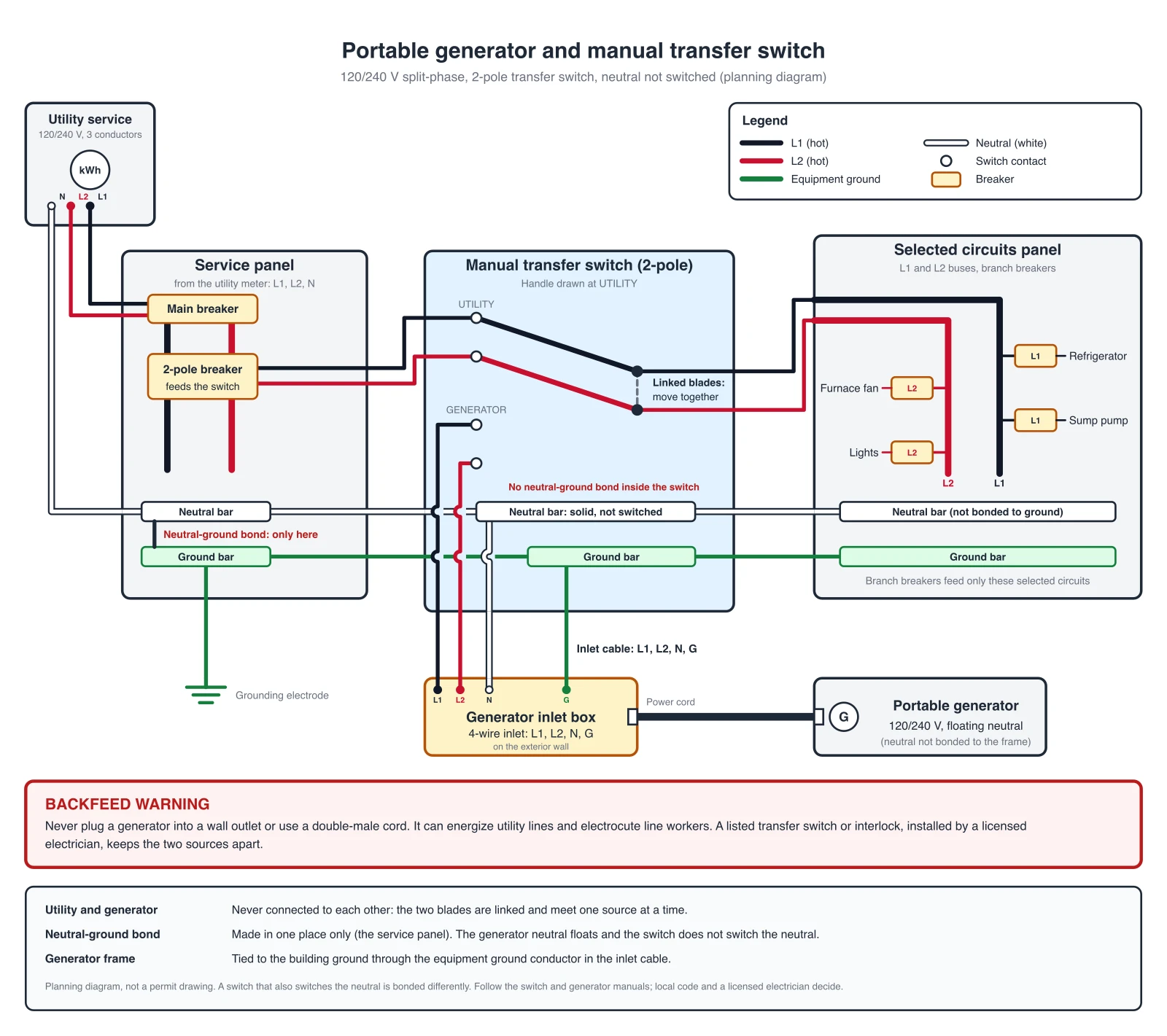 Example: Exact reference for this setup (drawn in code, not the AI output)View full size
Preview is free on this page ·
Your transfer switch wiring diagram will appear here
AI diagrams are drafts. Check every conductor, the neutral and the ground before use.
Generator Transfer Switch Wiring Diagram Examples
Exact reference diagrams drawn in code from a checked wire list. AI drafts from the generator need checking against them.
Manual transfer switch and inlet box
Shows the single neutral-ground bond in the service panel, a neutral that runs through the switch without being switched, and a generator with a floating neutral. Two linked blades connect the selected circuits to the utility or to the inlet, never both, and the inlet cable carries L1, L2, N and G. Drawn in code from a checked wire list. A planning diagram, not a permit drawing.
Main breaker interlock
Shows a main breaker and a backfed generator breaker joined by an interlock slide plate so only one can be on. The single neutral-ground bond is in the main panel, the neutral stays solid, and the generator has a floating neutral. The inlet cable lands on L1, L2, N and G. The kit must be listed for the panel model. Drawn in code from a checked wire list. A planning diagram, not a permit drawing.
Whole-house service-entrance ATS
Shows the single neutral-ground bond at the service disconnect inside the ATS, a neutral that is not switched, and a standby generator with a neutral that is not bonded. The downstream distribution panel keeps neutral and ground separate. A two-wire start signal runs from the ATS controller to the generator. Drawn in code from a checked wire list. A planning diagram, not a permit drawing.
Standby ATS and essential loads panel
Shows the main panel feeding the ATS through a 2-pole breaker, with the ATS powering only an essential loads panel. The single neutral-ground bond is in the service panel, the neutral is not switched, and the ATS and essential loads panel keep neutral and ground separate. The generator neutral is not bonded, and a two-wire start signal runs from the ATS controller to the generator. Drawn in code from a checked wire list. A planning diagram, not a permit drawing.
For other wiring, such as home, automotive, or appliance systems, use the Wiring Diagram Maker. Planning an EV charger circuit on the same panel? See the EV Charger Wiring Diagram Generator. For 12V and DC battery systems, try the Battery Wiring Diagram Generator, and for site-level power drawings with feeders and transformers, the Single-Line Diagram Generator.
Safety and code references (accessed October 2026): OSHA, Using Portable Generators Safely, OSHA, grounding portable generators, and NFPA 70, National Electrical Code.
What a generator transfer switch wiring diagram shows
A generator transfer switch wiring diagram shows how a generator connects to a building without ever feeding the utility. It has four parts: the utility source and the main panel, the transfer device (a manual switch, an interlock kit or an automatic transfer switch), the generator and its inlet, and the circuits that stay powered. It also shows the neutral and the ground, because those two decide whether the installation is safe. Homeowners use it to brief an electrician, electricians use it to quote and hand over, and installers use it to explain an ATS to a customer. Describe your installation in the prompt box, generate a draft, and compare it with the exact diagrams in the gallery above.
Why the two sources must never meet: backfeed
- A generator wired to a house without proper transfer equipment can send power back out through the service and onto the utility lines. That is called backfeed, and it can electrocute utility workers and others who think the lines are dead.
- OSHA’s fact sheet “Using Portable Generators Safely” (OSHA 3286) says that attaching a generator directly to a building electrical system without a properly installed transfer switch can energize wiring for great distances and endanger utility workers. A separate OSHA fact sheet on grounding portable generators, based on the construction standard, says the transfer switch must be approved for the use and installed by a qualified electrician following the maker’s instructions, and refers to an open-transition (break-before-make) transfer switch. Both are linked below and were accessed October 2026; the grounding sheet dates from 2005.
- Plugging a generator into a wall outlet with a double-male cord has the same problem. Do not do it.
- Every exact diagram on this page is built around one rule: the utility and the generator are never connected to the same load at the same time.
Manual transfer switch with a generator inlet box
- A manual transfer switch is a small panel that sits next to the main panel. A 2-pole breaker in the main panel feeds it, and a few selected circuits, such as the refrigerator, a furnace fan, a sump pump and some lights, are moved to it.
- Two linked blades, one for each hot conductor, connect those circuits either to the utility or to the generator. Because the blades move together, the two sources cannot be joined.
- The generator plugs into an inlet box on the outside wall, usually a 4-wire inlet carrying L1, L2, neutral and ground. A short cord links the generator to the inlet.
- The first exact diagram in the gallery draws this arrangement. The rating of the inlet, the switch and the cord must suit the generator, so take them from the equipment manuals.
- Carbon monoxide: run a generator outdoors only, well away from doors, windows and vents. The inlet box on the outside wall exists so the generator never has to run indoors or in a garage.
Interlock kit on the main panel
- An interlock kit is a mechanical plate that keeps the main breaker and a generator breaker from being on at the same time. The generator breaker, a 2-pole backfeed breaker, feeds the panel busbars through a 4-wire cable from the inlet box.
- The kit is made for a specific panel and is listed for it, so an electrician picks the kit that matches the panel model. A generic plate is not a substitute.
- Many local authorities and utilities restrict interlock kits, require a permit and inspection, or do not accept them at all. Ask before you buy one.
- With the interlock, the whole panel can be powered, so the generator and its wiring need to be sized for what you will run. Load planning is part of the electrician’s job.
Automatic transfer switch (ATS) for a standby generator
- An automatic transfer switch watches the utility. When the utility fails it signals the standby generator to start, waits until the generator is ready, then moves the load to it. When the utility returns it transfers back and lets the generator stop.
- Many whole-house installations use a service-entrance rated ATS, which sits between the meter and the main distribution panel and also acts as the service disconnect. Others use a smaller ATS next to the main panel for selected circuits.
- Inside, it is the same idea as the manual switch: linked blades that connect the load to one source at a time. The extra parts are the control wires, the sensing and the start signal drawn as a dashed line in the two ATS diagrams in the gallery. The service-entrance diagram shows a whole-house setup, and the essential-loads diagram shows an ATS fed from the main panel that powers only a few circuits.
Neutral switching and the neutral-ground bond
- The neutral and the ground are joined (bonded) at one place in a system, and not at a second place. A second bond lets normal neutral current flow on the ground path.
- If the transfer switch does not switch the neutral, the neutral runs straight through. The bond stays at the service, and the generator is used with its neutral floating, which means the neutral is not bonded to the generator frame. This is the arrangement in all four exact diagrams in the gallery, with the bond in the service panel, or in the service-entrance ATS for the whole-house case.
- If the transfer equipment also switches the neutral, the generator is treated as its own source and the bonding is arranged differently. Follow the transfer equipment and generator manuals, because the answer depends on the product and the local code.
- Many portable generators ship with the neutral bonded to the frame. If such a generator is connected through a switch that does not switch the neutral, the result is a second neutral-ground bond, which puts normal neutral current on the ground path and is dangerous. Follow the generator manual: remove the bond or use a bonding plug only as the manual allows, or use a transfer switch that switches the neutral. Do not change the wiring yourself, and have an electrician confirm the combination.
- OSHA’s 2005 grounding fact sheet, based on the construction standard, says a portable generator that powers a structure through a transfer switch must be connected to a grounding electrode system, and points to Article 250 of the National Electrical Code for the grounding rules. Check the edition your jurisdiction has adopted (OSHA sheets accessed October 2026).
How to generate a generator transfer switch wiring diagram from text
- Say which arrangement you want: manual transfer switch with an inlet box, main breaker interlock kit, or automatic transfer switch. One drawing per prompt gives better results.
- Name the voltage and system, for example 120/240 V split-phase, and the conductors on each run: L1, L2, neutral and ground.
- State where the neutral-ground bond sits, whether the neutral is switched, and whether the generator has a floating neutral.
- List the selected circuits for a manual switch, or say whole house for an ATS.
- Ask for generic components, no brand names, short English labels and a legend. Generate, then trace every conductor, especially the neutral and the ground, and re-prompt to fix anything that is wrong.
Exact reference diagrams vs AI drafts
The four examples in the gallery are exact reference diagrams. They are drawn in code from a checked wire list, so every wire and label is placed on purpose. We do not show AI-generated wiring images as examples, because image models often draw wrong connections. In our own tests we saw a neutral touching a ground bar inside the switch, which makes a second neutral-ground bond, a utility conductor run to the generator, poles drawn in the wrong colors, and feeders that stop at the enclosure edge instead of landing on a terminal. The generator on this page still produces an AI draft from your prompt. Treat that draft as a rough layout, check every connection against the exact references and the equipment manuals, and let a licensed electrician decide what gets installed. A diagram from this page is a planning sketch. It is not a permit drawing, a wire list or a bill of materials, and it does not replace the electrical code that applies in your area.
Codes and sources
In the United States, standby power and grounding are covered by the National Electrical Code (NFPA 70), and states and cities adopt different editions, so ask your local authority which one applies. Diagrams from this page do not claim compliance with any code. This page does not state section numbers of its own, because wording changes between editions.
Frequently Asked Questions
Related Engineering Tools
PhysicsWiring Diagram Maker
Wiring diagrams for home, automotive, appliance, and industrial systems from a plain-English description.
 Engineering
EV Charger Wiring Diagram Generator
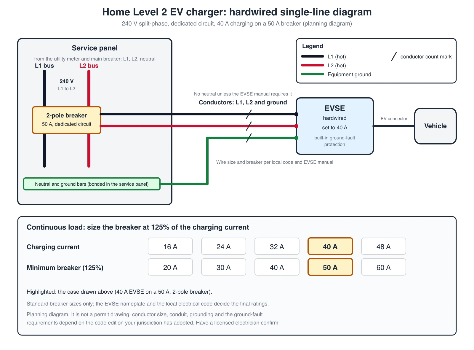
Home Level 2 and NEMA 14-50 outlet diagrams, with an exact hardwired single-line diagram.
 Engineering
Battery Wiring Diagram Generator
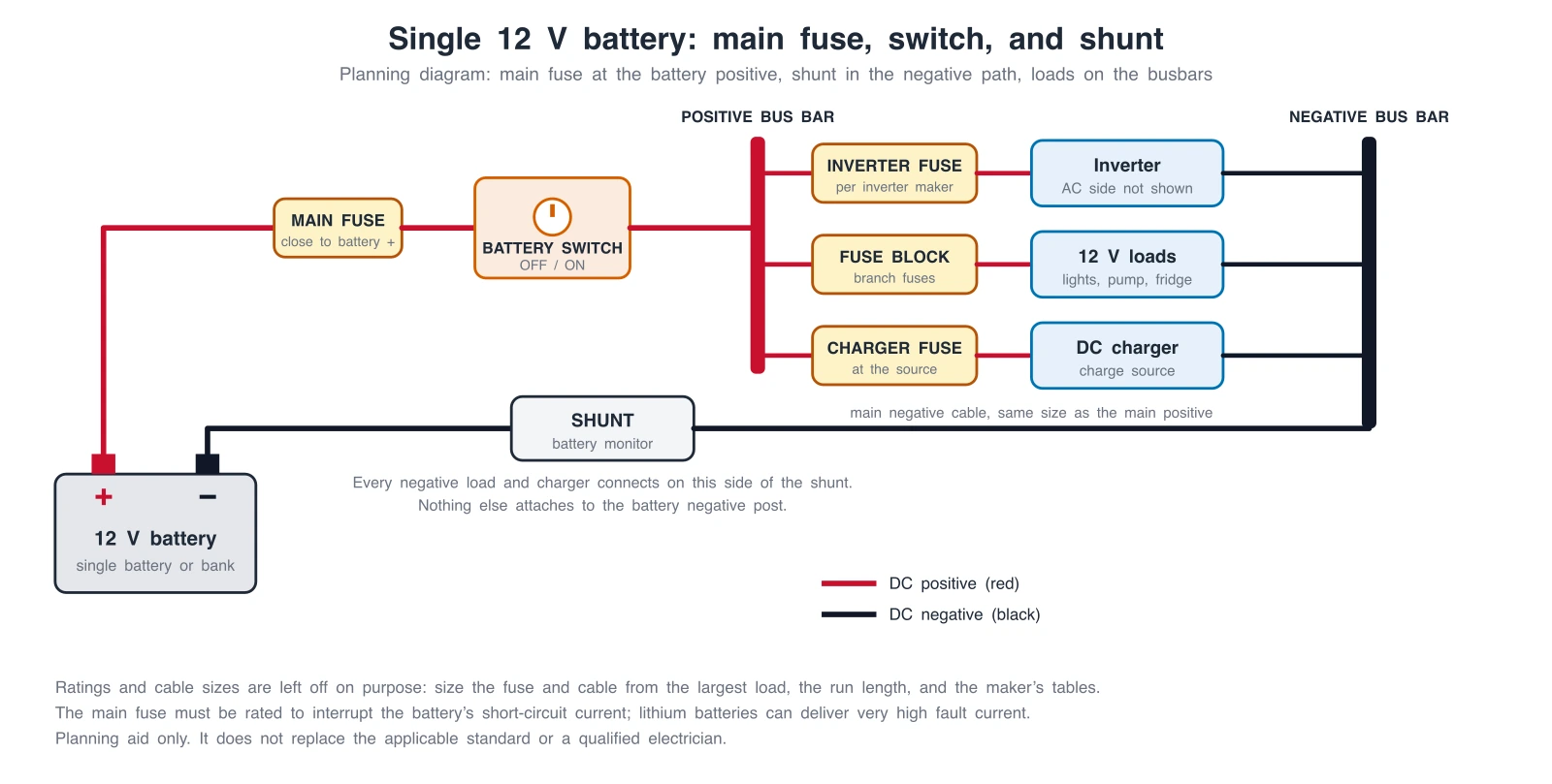
Generate battery wiring diagrams: main fuse, switch, shunt, series or parallel banks, and DC-DC charging, with exact reference diagrams.
 Engineering
Single-Line Diagram Generator
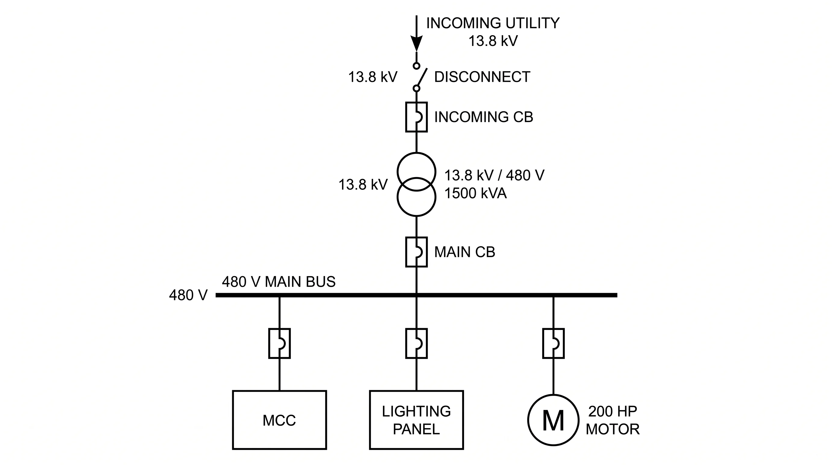
Facility-level one-line diagrams of sources, transformers, and feeders.