Solar Panel Wiring Diagram Generator Series, Parallel, and Off-Grid
Generate a solar panel wiring diagram from a prompt. Exact examples for series, parallel, 2S2P to MPPT, and a full off-grid chain with fuses.
Create Your Solar Panel Wiring Diagram
 Example: Exact reference for this setup (drawn in code, not the AI output)View full size
Preview is free on this page ·
Your solar panel wiring diagram will appear here
AI diagrams are drafts. Check every connection, fuse, and polarity before use.
Solar Panel Wiring Diagram Examples
Exact reference diagrams drawn in code from a checked wire list, with example panel numbers. AI drafts from the generator need checking against them.
Two solar panels in series (exact diagram)
Drawn in code, not by AI, with example 200 W panels (Voc 22.5 V, Vmp 18.5 V, Isc 11.5 A, Imp 10.8 A). The positive of panel A goes to the negative of panel B. Voltages add (45 V Voc, 37 V Vmp) and current stays at 10.8 A. The caption also shows the cold-weather Voc: 49.7 V at −10 °C with a −0.30 %/°C example coefficient. Panel symbols are simplified, and the numbers are examples, not your panels.
Two solar panels in parallel (exact diagram)
Drawn in code. Both negatives join one rail and both positives join the other. Voltage stays the same (22.5 V Voc, 18.5 V Vmp) and currents add to 21.6 A at maximum power and 23 A short-circuit. It notes that cable and protection are sized for the combined current. Example panel numbers; check your datasheet.
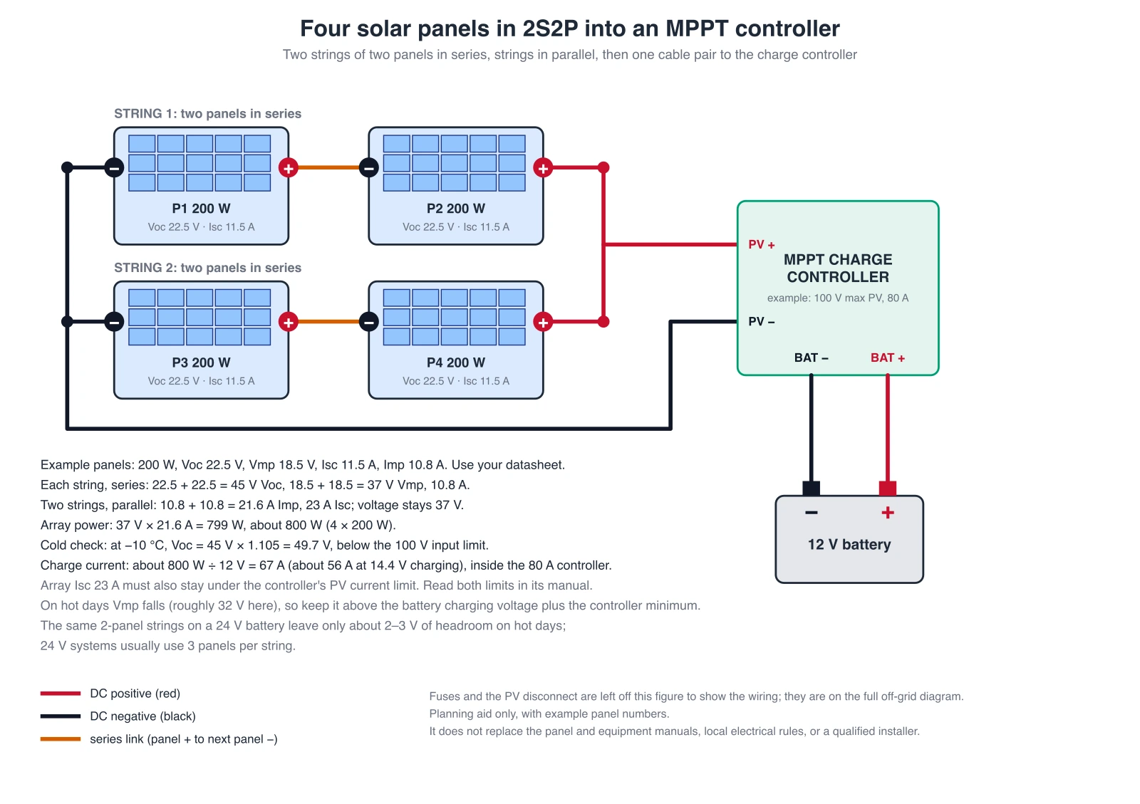
Four panels in 2S2P into an MPPT controller (exact diagram)
Drawn in code. Two strings of two panels in series, joined in parallel: 45 V Voc, 37 V Vmp, 21.6 A, about 800 W. The cold-weather check (49.7 V at −10 °C) is compared with an example 100 V controller limit, and the charge current (about 67 A at 12 V, about 56 A at 14.4 V charging) with an example 80 A controller. It also notes that on a 24 V battery these 2-panel strings leave little hot-day headroom, so 24 V systems usually use 3 panels per string. Fuses and the PV disconnect are left off this figure and shown on the next one.
Off-grid chain: array, combiner, controller, battery, inverter (exact diagram)
Drawn in code. String fuses sit in the combiner on each positive, a 2-pole DC-rated disconnect opens both PV conductors, the controller output and the inverter each get a fuse close to the battery positive, and all negatives return to the battery negative. Ratings are left off on purpose. Shunt, bus bars, earthing and bonding are not shown, and the main battery fuse and switch are covered on the battery wiring page.
For the battery side, including main fuse, switch, shunt, and series or parallel batteries, see the Battery Wiring Diagram Generator. For boat systems, use the Boat Wiring Diagram Generator, and for other wiring diagrams, the Wiring Diagram Maker. For drawing conventions see how to make a wiring diagram.
What a solar panel wiring diagram shows
A solar panel wiring diagram shows how panels connect to each other and to the rest of the system: which terminal joins which, how many panels sit in series in each string, how strings are paralleled, and where the fuses, disconnect, charge controller, battery, and inverter go. The same few patterns appear in RVs, vans, boats, sheds, and off-grid cabins. Describe your panels and parts in the prompt box, generate a draft, and compare it with the exact reference diagrams in the gallery above. The AI draft is only a starting point and needs checking.
Series vs parallel: voltage or current
- Series connects the positive of one panel to the negative of the next. Voltages add and current stays the same. Two 200 W panels with Voc 22.5 V and Imp 10.8 A make 45 V Voc and 10.8 A.
- Parallel connects positive to positive and negative to negative. Voltage stays the same and currents add. The same two panels make 22.5 V Voc and 21.6 A at maximum power.
- Power is the same either way, about 400 W here. Pick series when the controller or inverter wants a higher input voltage (and you want thinner cable), and parallel when you need to stay at a lower voltage, for example with a PWM controller or a short-run 12 V system.
- Use panels of the same model in one string. In a series string the weakest panel limits the current, and one shaded panel can pull the whole string down. In parallel, a shaded panel only loses its own share.
Series-parallel (2S2P): the arithmetic
- Four panels can be wired as two strings of two in series (2S2P), with the two strings in parallel. Work from the string up: each string of two example panels gives 45 V Voc, 37 V Vmp, and 10.8 A. Two strings in parallel keep the voltage and add the current: 37 V and 21.6 A, which is about 800 W (37 V × 21.6 A = 799 W).
- The short-circuit current adds in the same way: 11.5 A × 2 = 23 A. Cable, connectors, and protection must be sized for that combined current, not for one string.
- A parallel junction is made with branch connectors or a combiner box. With two strings, check the panel datasheet for its maximum series fuse rating. With three or more strings in parallel, each string normally needs its own fuse or breaker, because a fault in one string can be fed by the others.
Cold weather Voc and the controller input limit
- Open-circuit voltage goes up as the panels get colder. Take the Voc temperature coefficient from the datasheet (about −0.30 %/°C in this example) and multiply the array Voc by 1 + 0.003 × (25 − T), with T the coldest expected panel temperature in °C. At −10 °C the factor is 1.105, so a 45 V array reads about 49.7 V.
- That cold number, not the 45 V on the label, must stay under the maximum PV input voltage of the controller (100 V in this example) with some margin. It tells you how many panels can go in one series string: one panel is 22.5 V × 1.105 = 24.9 V cold, so 100 V ÷ 24.9 V is about 4.0. Four panels would sit right at the limit, so leave margin and use fewer, or pick a controller with a higher limit.
- Two more checks apply. The array short-circuit current (23 A here) must stay inside the controller’s PV current limit, and the charge current into the battery must stay inside the controller’s rating: about 800 W ÷ 12 V is 67 A (about 56 A at a 14.4 V charging voltage), so a controller rated about 70 to 80 A is needed; a 40 A controller would be overloaded. On hot days Vmp falls, so check that it stays above the battery charging voltage plus the controller’s minimum headroom. The same 2-panel strings on a 24 V battery leave only about 2 to 3 V of headroom on hot days; 24 V systems usually use 3 panels per string.
The off-grid chain: panels to inverter
- Panels go first to a combiner, where each string positive passes through its own fuse and the strings join on a positive and a negative rail. Next is a DC-rated disconnect that opens both the positive and the negative PV conductors, so the array can be isolated for maintenance. Then comes the charge controller.
- The controller output goes to the battery through a fuse or breaker placed close to the battery positive terminal. The inverter has its own cable to the battery, with its own fuse also close to the battery positive, sized from the inverter maker’s instructions. Negatives return to the battery negative, through a shunt if you use a battery monitor.
- Most charge controller manuals say to connect the battery first and the PV array second, and to disconnect in the reverse order. Check yours. Earthing and bonding of the frames and the system are not drawn on the exact diagrams; follow the equipment manuals and the rules where you live. The battery wiring diagram generator covers the battery side in more detail.
MPPT or PWM: how the wiring differs
An MPPT controller accepts a PV voltage well above the battery voltage and converts it down, so panels can be wired in series to cut the current and use thinner cable. A PWM controller passes the panel voltage almost straight to the battery, so the panel voltage must match the battery’s nominal voltage: 12 V-class panels in parallel for a 12 V battery, or two in series for a 24 V battery (36-cell panels leave little headroom when hot, so check the datasheet). This is why the same set of panels can have a different best layout with each controller type. Always check the controller’s maximum PV voltage and current in its manual before you choose a layout.
Fuses, cable, and voltage drop
Size each protective device and each cable from the current it carries, not from a gauge printed on a generated picture. In the US, a common starting point for a string fuse is 1.56 × the panel short-circuit current (11.5 A × 1.56 = 17.9 A, so the next standard size of 20 A), which must also stay at or under the maximum series fuse rating on the panel datasheet. Keep the PV voltage rating of the fuse or breaker above the cold array Voc, and use DC-rated parts, since a DC arc does not extinguish like an AC one. Longer runs need heavier cable to keep voltage drop small. AI-generated diagrams can print wrong or mismatched ratings, which is why the exact diagrams on this page leave them off.
Solar panel wiring for an RV or van
Small mobile systems usually use parallel on a 12 V battery; for 24 V use series pairs, or 3 panels per string with an MPPT. Use a PWM or MPPT controller, with panels joined at the roof with branch connectors, with the combined current in mind. Cable passes into the vehicle through a roof gland, then to the controller close to the battery. Put the fuse for the controller output near the battery, and keep the panel cable runs short. If the roof is shaded part of the day, think about which panels share a string. The battery wiring diagram generator covers the starter and house battery side, including a DC-DC charger.
Which rules apply to your installation
There is no single rule for every solar installation. In the United States, NEC Article 690 covers photovoltaic systems, and IEC 62548 is an international design standard for PV arrays; check the current edition and your local authority. Boats, vehicles, and cabins can have their own rules. Follow the panel, controller, battery, and inverter makers’ instructions and the rules where you live, and have a qualified electrician or installer review anything you build. A diagram from this page is a planning diagram, not a construction drawing.
How to generate a solar panel wiring diagram from text
- List the parts you actually have: panel count with Voc, Vmp, Isc, and Imp, the controller type and limits, battery voltage and chemistry, and the inverter.
- State the layout in words: panels per string, number of strings, and what the strings join on.
- Say where fuses, breakers, and the disconnect go, and which terminal each cable leaves from.
- Ask for red positive wires, black negative wires, short labels, and generic components with no brand names.
- Generate, then check every connection: polarity first, then fuse positions, then the voltage and current arithmetic.
- Re-prompt to fix anything wrong. If a cable ends on the wrong terminal, say which terminal it should use.
Exact reference diagrams vs AI drafts
The four examples in the gallery are exact reference diagrams. They are drawn in code from a checked wire list, and the series and parallel numbers in each caption are computed from that wire list, so every connection, polarity, and label is placed on purpose. We do not show AI-generated wiring images as examples, because image models often draw wrong connections: a series link joined positive to positive, a string wired backwards, a fuse on the wrong side, or a controller with no battery. The generator on this page still produces an AI draft from your prompt. Treat that draft as a rough layout, check every connection against the exact references and the equipment makers’ manuals, and let a qualified installer decide what gets built. A diagram from this page is a planning diagram. It is not a traced schematic or a wire list.
Frequently Asked Questions
Related Engineering Tools
 Engineering
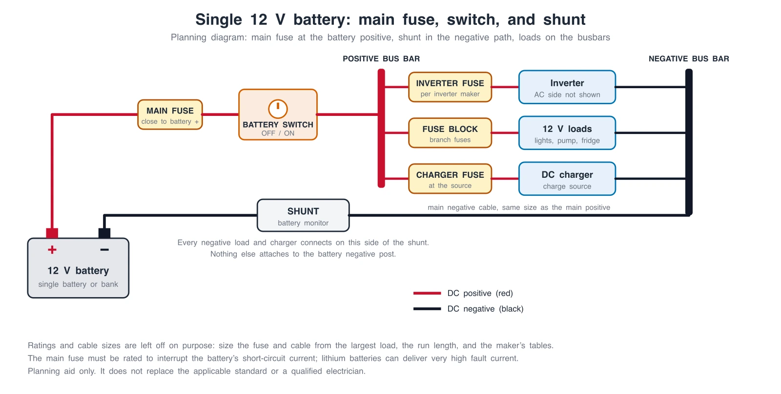
Battery Wiring Diagram Generator
Battery banks: main fuse, switch, shunt, series or parallel batteries, and DC-DC charging.
 Engineering
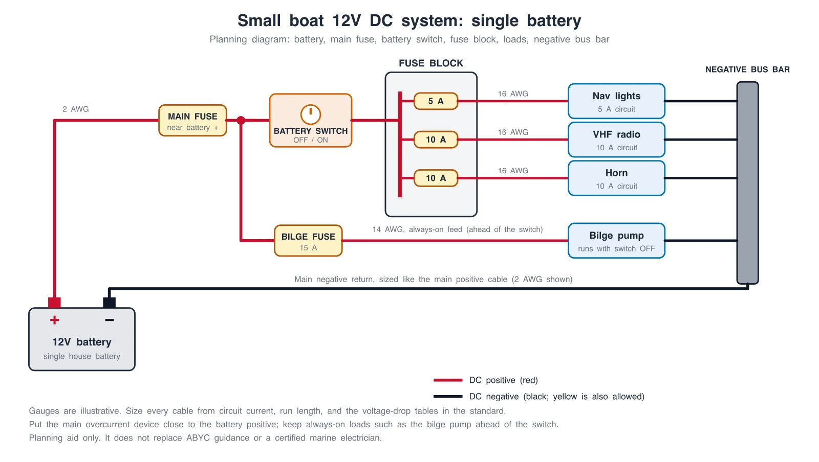
Boat Wiring Diagram Generator
Boat 12V systems: single and dual battery, battery switch, fuse block, bilge pump, and outboard.
 Physics
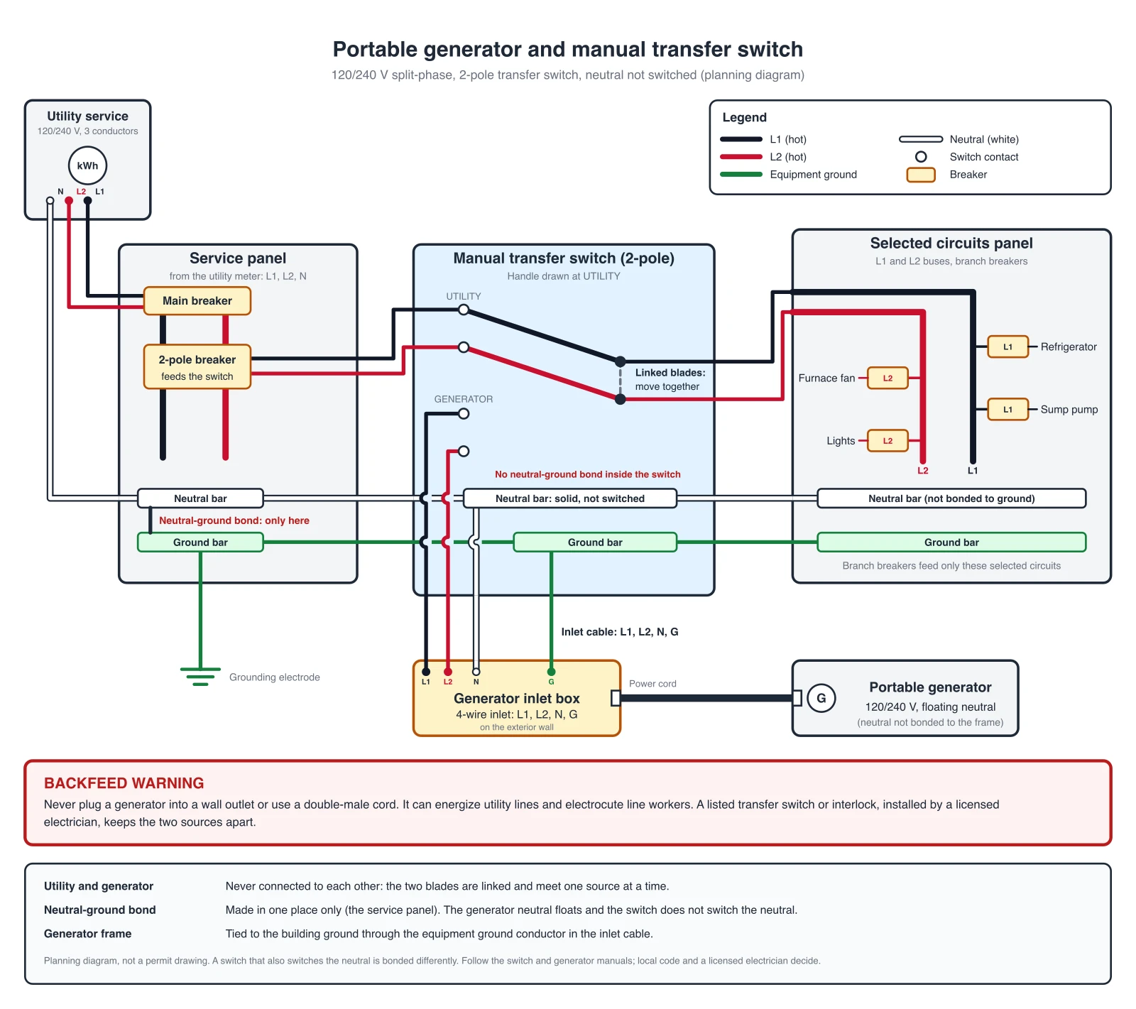
Wiring Diagram Maker
Wiring diagrams for home, automotive, appliance, and industrial systems from a plain-English description.
 Engineering
Single-Line Diagram Generator
Facility-level one-line diagrams of sources, transformers, and feeders.