Single-Line Diagram Generator for Electrical One-Line (SLD)
Create an electrical single-line diagram draft. Explore precise one-line examples, IEEE and IEC symbol guidance, generator ATS layouts, and an SLD checklist.
Single-Line Diagram Generator
Preview is free on this page ·
Your single-line diagram will appear here
Describe your SLD and click Generate
Single-Line Diagram Examples
Two precise references followed by four AI teaching drafts. Read the assumptions and omissions in each caption.
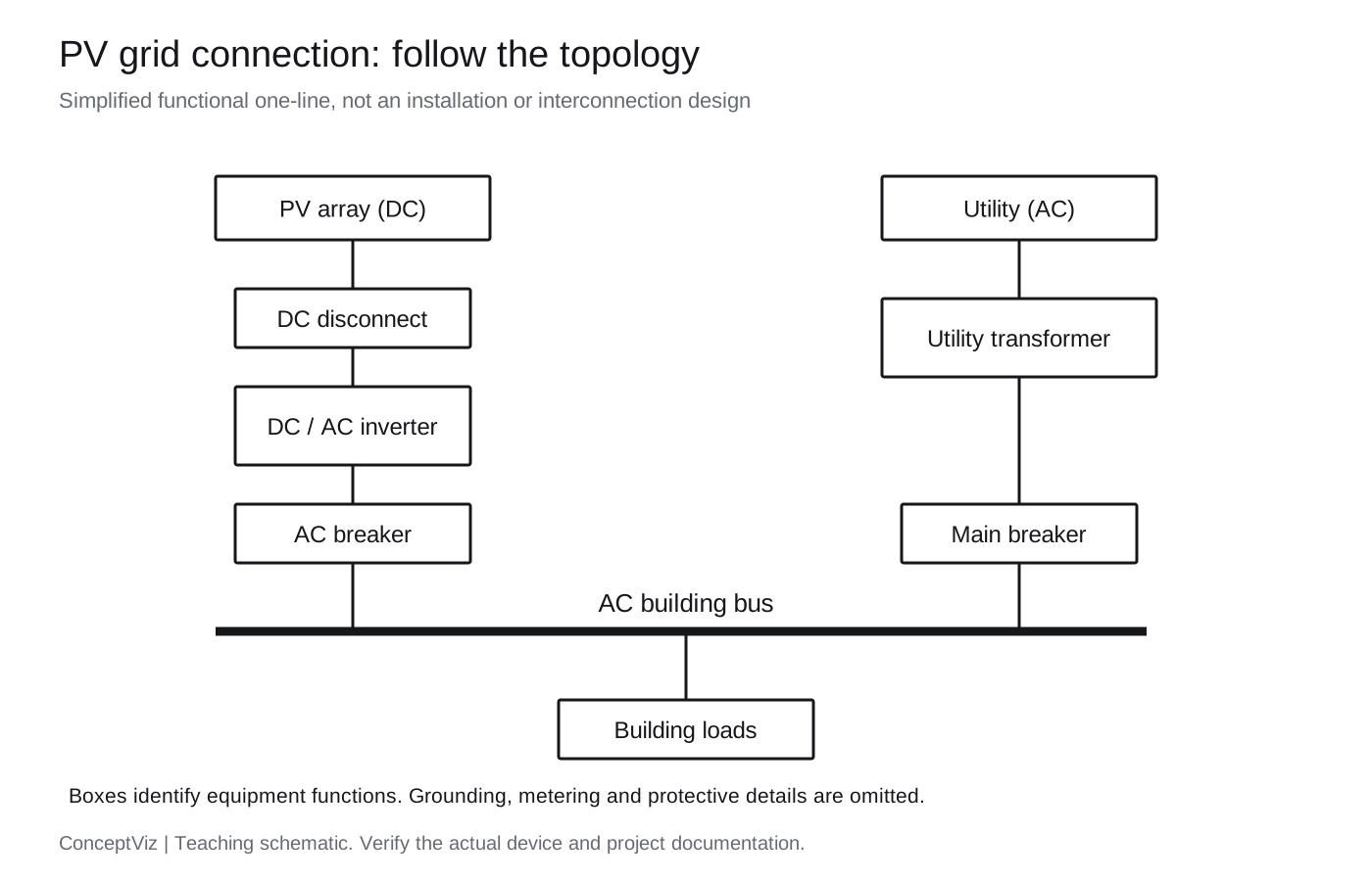
PV connection: exact reference
Exact teaching diagram. Trace the PV and utility branches to their common AC bus. Equipment boxes show functions, not a complete standards symbol set.
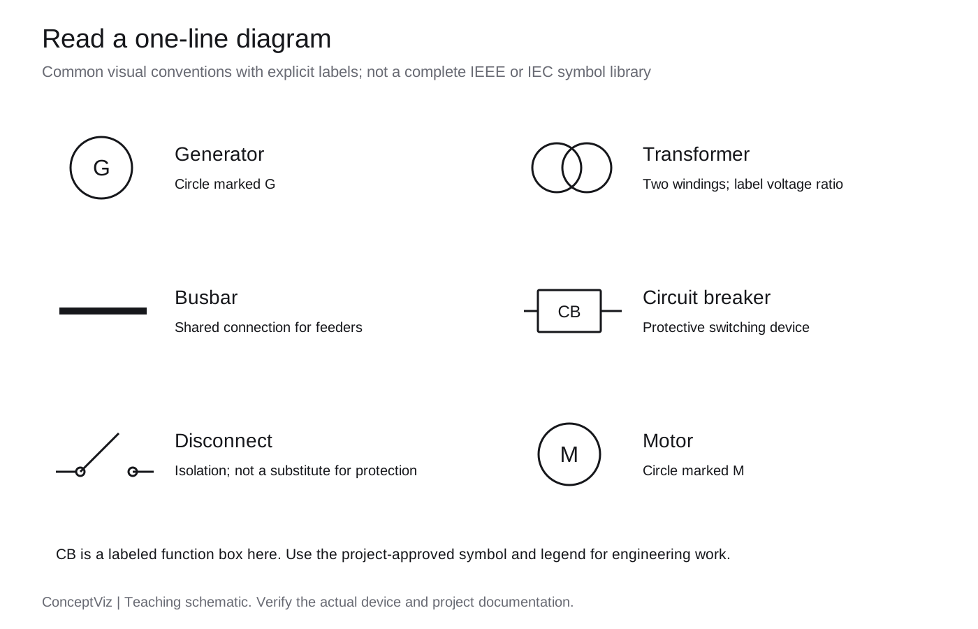
Symbols: exact reading guide
Exact reference with explicit labels. The breaker is a function box. Select project-approved symbols before engineering use.
Utility to MCC: AI draft
AI illustration of source, transformer, main breaker and three feeders. Ratings are hypothetical; this is not an equipment schedule.
Generator with ATS: AI draft
AI illustration using an ATS function block. It does not show its internal switching, neutral arrangement or transfer sequence. Never infer permission to parallel the sources.
Substation: AI draft
AI illustration of feeder topology. Station-service protection and grounding details are omitted; the drawing is incomplete for design or field use.
Blank planning worksheet: AI draft
A planning exercise for labeling equipment functions. These blank boxes are not standardized power-system symbols.
Download PV reference SVGDownload symbol reading guide SVG
IEEE and IEC symbols: choose a convention, then verify it
A label such as “IEEE/IEC” is not a complete drawing specification. Choose the convention required by the project and identify it in a legend. The IEC TC 3 explanation identifies IEC 60617 DB as the standard database of graphical symbols for diagrams; full database access requires a subscription. We have not reproduced or certified that library here.
The IEEE 315 catalog covers graphical symbols and reference designations for electrical and electronics diagrams. IEEE currently lists IEEE/ANSI 315-1975 as Inactive-Reserved, with an inactivation date of November 7, 2019. It remains a reference you may encounter in existing drawings; do not describe it as a newly active standard. Official records checked October 10, 2026.
| Element | Read on the drawing | Confirm in project data |
|---|---|---|
| Transformer | Windings and the labeled voltage ratio | Rating, winding connections and grounding |
| Bus | A shared connection for incoming and outgoing circuits | Voltage, phase arrangement and rating |
| Circuit breaker | Protective switching device, identified by tag | Device type, trip data and interrupting rating |
| Disconnect | An isolation/switching function | Whether it is rated for the intended switching duty |
| Generator / motor | Machine symbol with G or M and a tag | Supply or load role, rating and connection |
| ATS / bus tie | Which source or bus is connected in each state | Interlocking, normal state and transfer arrangement |
The precise examples use labeled functional blocks where a project-specific symbol would be needed. For individual terminals, use the Wiring Diagram Maker; for operating logic, use the Schematic Diagram Maker. Our 4-pin and 5-pin relay guide shows why pin-level connections need a different view.
What is a single-line diagram (one-line / SLD)?
A single-line diagram is a map of an electrical power system. In a three-phase system, one line commonly represents the three phase conductors; other arrangements must be identified in the drawing notes. Follow the source through transformers and switching equipment to buses, outgoing feeders and loads. The drawing records electrical topology and selected ratings rather than the physical route of every wire. It is useful for reading a facility supply, discussing an expansion or teaching power distribution. It is not a continuous-line art drawing, and a simplified teaching SLD does not supply the information needed to build or operate the installation.
Read the system in five passes
- Find every source: utility supply, standby generator, solar inverter, battery or other supply. Do not assume that opening one device removes every possible source.
- Follow each source to its transformer and incoming switching or protection. Check the voltage on both sides of each transformer; do not put the high-side voltage on a low-voltage bus.
- Trace the bus connections. A junction means electrical connection; crossing lines without the specified junction convention do not automatically connect. Identify normally open ties.
- Follow every feeder to a named destination. Match equipment IDs, voltage and device ratings to verified design data rather than filling gaps with guessed values.
- Read the legend and notes. Phase count, neutral, grounding, protection, metering and normal switching states may require separate drawings. A one-line is a summary, not proof that the system is safe to energize.
Single-line vs schematic vs wiring diagram
- Single-line / one-line: the supply and distribution topology, principal equipment, selected ratings and protection. One line can summarize a multiphase circuit.
- Schematic diagram: functional electrical relationships, which can include power circuits as well as control and electronic circuits. It need not resemble the physical arrangement.
- Wiring diagram: identified terminals and conductor connections, often with routing, cable and color information. Use the wiring diagram maker for a connection draft and the schematic diagram maker for circuit operation.
- For a small automotive relay, a terminal-level wiring diagram explains more than a power-system one-line. For a building supply and its feeders, an SLD keeps the overall system readable.
Describe a generator SLD or utility system clearly
Start with the sources, their voltage and phase arrangement. List transformer ratios, the distribution buses, main and feeder devices, and named loads such as an MCC, panel or motor. For generator backup, identify the utility and generator as separate ATS inputs and the load as the output. State the intended transfer arrangement; a generic ATS block does not establish closed-transition or paralleling capability. Supply known ratings only. Ask for a legend, equipment tags and a clear normal operating state. The existing utility, generator, substation, solar and blank-workbook topics remain available in the examples.
Review an AI draft before sharing it
- Trace continuity from each source to each load. Look for disconnected line ends, accidental junctions, missing equipment and a transformer connected on the wrong side.
- Compare the illustration with the requested topology and your source documents. Check every voltage, transformer ratio, equipment identifier and protective-device label.
- Use one declared symbol convention and an explicit legend. A breaker, isolator and fuse perform different functions even when a draft renders all three as a box.
- Reject illegible labels and impossible connections. Redraw the affected region in a diagram editor or request a corrected draft, then inspect it again.
- Use these outputs for explanation and review. Permit drawings, protection coordination and arc-flash work need verified system data and qualified professional review; generating a picture does not perform those studies.
Frequently Asked Questions
Related Engineering Tools
 Engineering
Circuit Diagram Maker
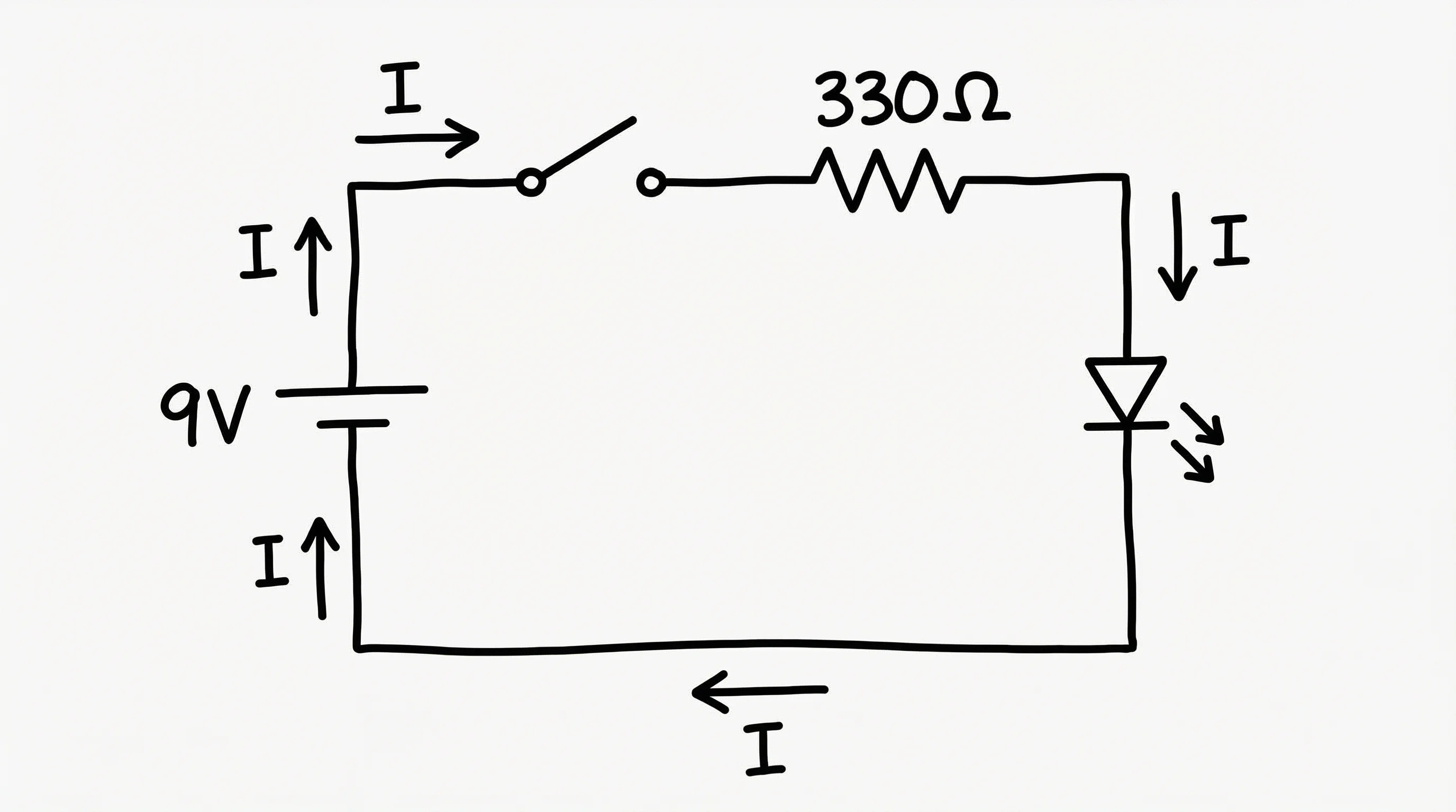
Electronics schematics with resistor, capacitor, and IC symbols ; not a power one-line.
 Engineering
Wiring Diagram Maker
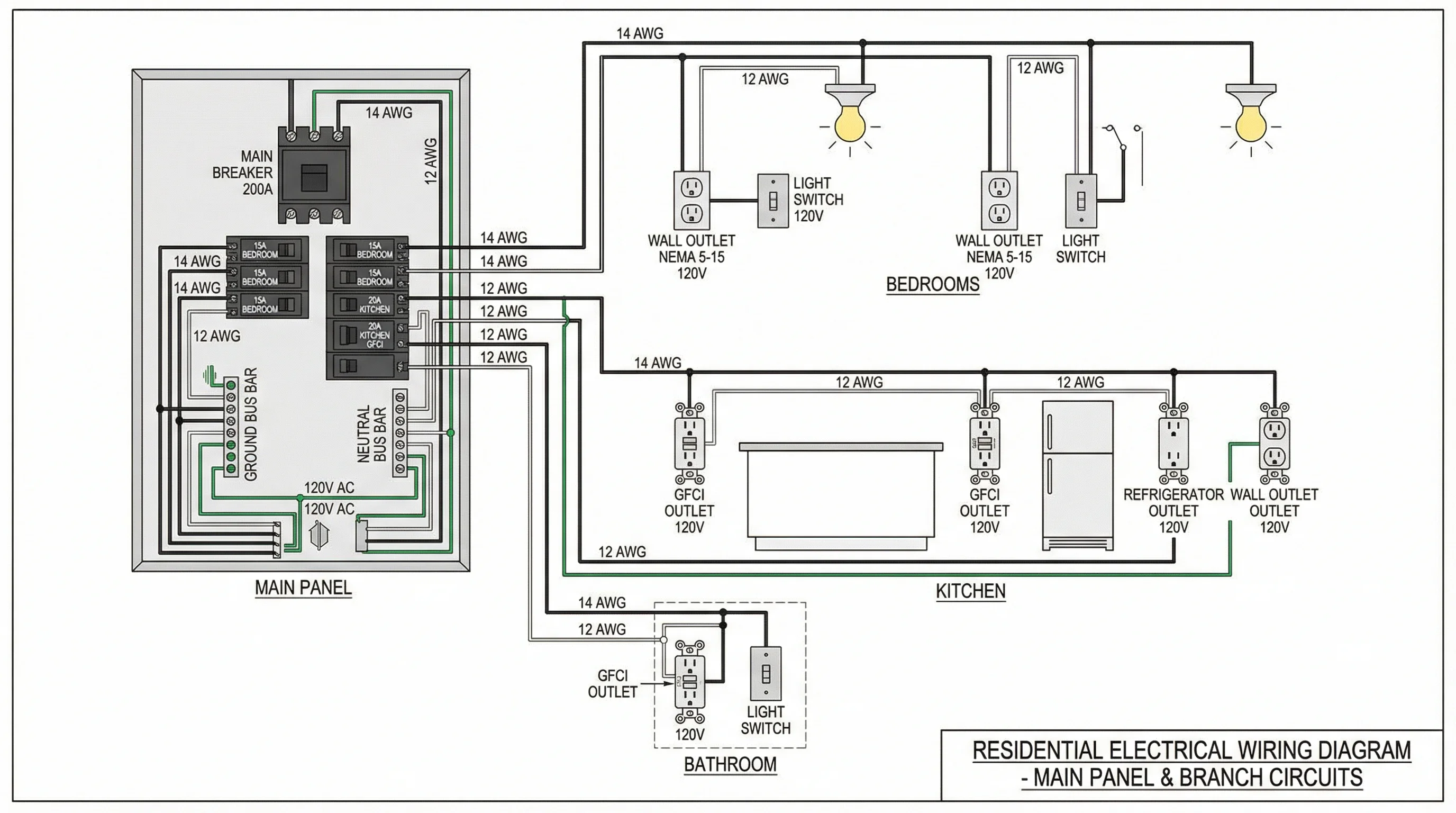
Physical wire routing, colors, and terminals for installation drawings.
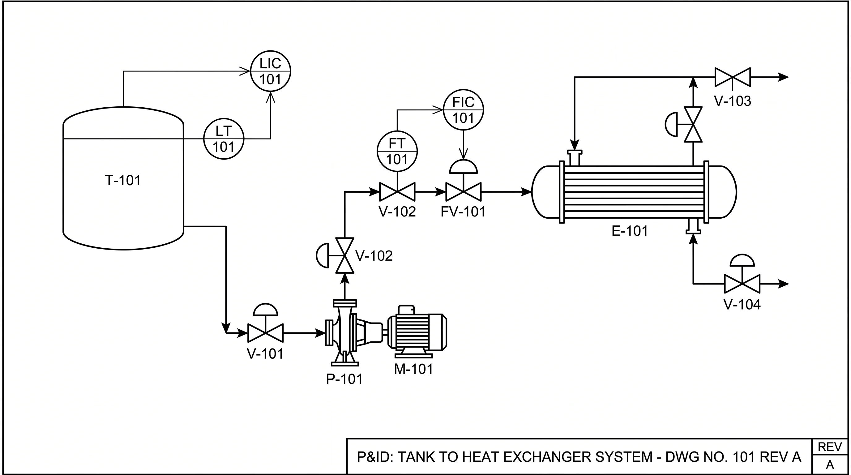 Engineering
P&ID Maker
Piping and instrumentation diagrams with ISA symbols for process plants.