EV Charger Wiring Diagram Generator for Home Level 2 Charging
Generate an EV charger wiring diagram from text: home Level 2 hardwired and NEMA 14-50 outlet installs. With an exact hardwired single-line diagram.
Create Your EV Charger Wiring Diagram
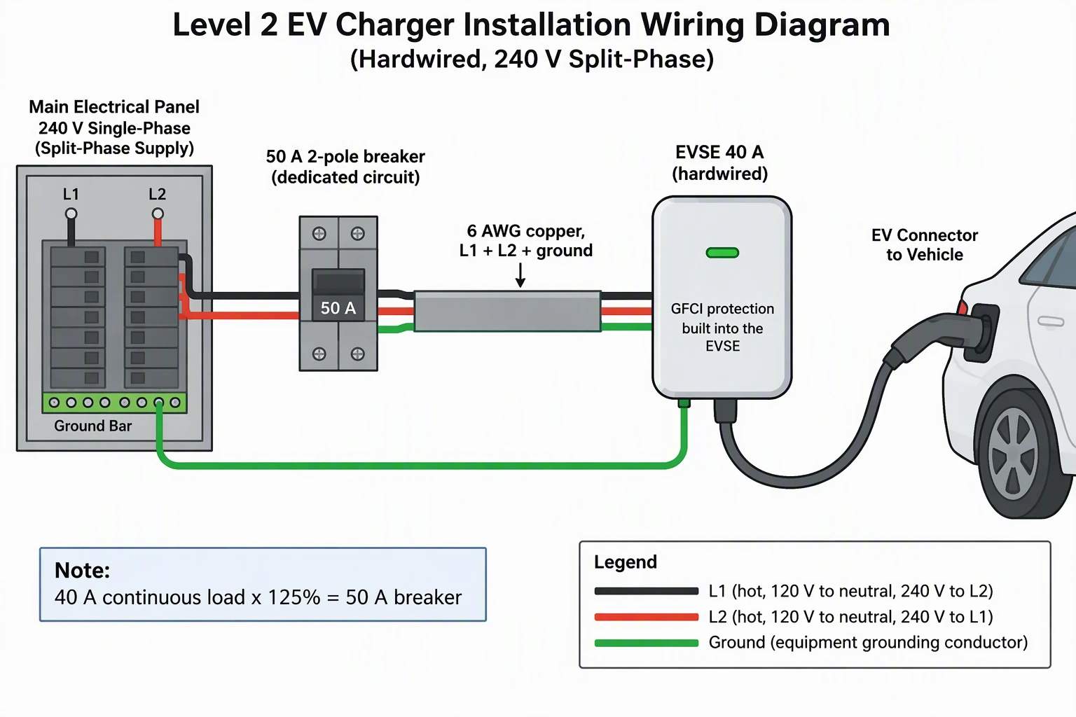 Example: Home Level 2, hardwiredView full size
Preview is free on this page ·
Your EV charger wiring diagram will appear here
AI diagrams are drafts. Check every conductor, breaker rating, and ground connection before use.
EV Charger Wiring Diagram Examples
One exact diagram drawn in code, plus two AI diagrams with their known flaws noted. AI diagrams need human review.
Home Level 2 hardwired single-line diagram (exact diagram)
Drawn in code, not by AI. A dedicated 2-pole breaker takes L1 and L2 from the panel, the run to the EVSE carries L1, L2 and an equipment ground with no neutral, and the ground returns to the bonded neutral and ground bars. The table applies the continuous-load rule: breaker at 125% of the charging current, so 40 A charging calls for a 50 A breaker. Conductor size is left to the local code and the EVSE manual on purpose, and the diagram is a planning sketch, not a permit drawing.
Home Level 2, hardwired (AI diagram)
AI-generated from a prompt close to the one shown. We checked it: dedicated 2-pole 50 A breaker, L1 and L2 plus ground with no neutral, 40 A x 125% = 50 A, a ground run from the panel ground bar to the EVSE, and ground-fault protection credited to the EVSE. Known flaws: the breaker is drawn as a separate box outside the panel; the ground is drawn both inside the cable and as a second run from the ground bar; the legend mentions 120 V to neutral although no neutral is drawn; the car is cropped at the edge; the 6 AWG size is only an example.
NEMA 14-50 outlet installation (AI diagram)
AI-generated from a prompt close to the one shown. We checked it: dedicated 2-pole 50 A breaker, a 4-wire cable, a rear view of the receptacle terminals with a black wire on L1, a red wire on L2, a white wire on N and a green wire on G (each terminal labeled once), a front view with two hot slots, a neutral slot and a ground pin, and 40 A continuous on a 50 A breaker. Known flaws: near the box the red and green wires overlap, so the red wire cannot be traced all the way back to the cable; the panel shows no neutral and ground bar and no ground-fault protection; the front view is schematic and real devices can be mounted in other orientations; the car is cropped at the edge. the cable is not connected to the breaker that is drawn; the portable EVSE plug hangs in the air instead of plugging into the receptacle; the terminal layout in the rear view is schematic. Wire your own receptacle by its terminal markings and the EVSE manual, not by wire color in a picture. Earlier attempts were discarded: one drew a green wire at the L1 terminal and labeled the ground twice, and another had a wrong receptacle face and called neutral 120 V.
For wiring outside EV charging, such as home, automotive, or appliance systems, use the Wiring Diagram Maker. For site-level power drawings with feeders and transformers, see the Single-Line Diagram Generator. For 12V and DC battery systems, try the Battery Wiring Diagram Generator, and for motor starters and PLC panels, the Control Panel Wiring Diagram Generator.
Code reference (checked October 2026): NFPA 70, National Electrical Code.
What an EV charger wiring diagram shows
An EV charger wiring diagram shows how power gets from the service panel to the charger, and what protects it on the way. For a home it is a short chain: the panel, a dedicated 2-pole breaker, the cable run, the charger (called EVSE, electric vehicle supply equipment), and the ground path. Homeowners use it to brief an electrician, electricians use it to quote and hand over, and property managers use it to plan charging spaces. Describe the installation in the prompt box, generate a draft, and compare it with the exact diagram in the gallery above.
Home Level 2 charger: the hardwired circuit
- A Level 2 charger runs on 240 V. In a US split-phase home, that is the voltage between the two hot conductors, L1 and L2.
- The chain is: service panel, a dedicated 2-pole breaker, a cable carrying L1, L2 and an equipment ground, then the EVSE. Dedicated means the circuit feeds only the charger.
- The ground returns to the panel ground bar, which is bonded to the neutral in the service panel. The exact diagram on this page draws that path.
- Charging current is set on the EVSE, often with a dial or in an app. The breaker and the conductors are chosen to suit that setting, not the other way around.
The 125% rule: why a 40 A charger gets a 50 A breaker
- Charging an EV can run at full current for hours, so it is treated as a continuous load. The usual practice is to size the breaker at 125% of the charging current.
- In numbers: 16 A charging calls for a 20 A breaker, 24 A for 30 A, 32 A for 40 A, 40 A for 50 A and 48 A for 60 A. These are the standard breaker sizes that sit at or just above 125%.
- Many EVSE let you turn the current down. A 48 A unit set to 40 A needs a circuit that matches the setting and the nameplate, and the installer decides which.
- Conductor size follows the breaker and the code tables, so this page leaves it out of the exact diagram. Take it from the code edition your jurisdiction uses and the EVSE manual.
NEMA 14-50 outlet or hardwired
- A NEMA 14-50 receptacle is a 50 A, 4-wire outlet with two hot slots, a neutral slot and a ground pin. A portable EVSE plugs into it. It is popular because the same outlet also serves RVs and ranges, and because the charger can be unplugged and taken along.
- Plug-in EVSE on a 14-50 are usually limited to 40 A, which matches the 125% rule on a 50 A breaker.
- Hardwiring removes the plug and the receptacle from the circuit and allows higher currents, such as 48 A on a 60 A breaker. It also suits outdoor wall units, because there is no outlet to wear out.
- Either way the breaker is a dedicated 2-pole, and the receptacle must be rated for the circuit. Ask the EVSE maker whether it wants a plug or a hardwired feed, because the manual decides.
Neutral, ground and ground-fault protection
- Most Level 2 EVSE run on 240 V only, so the run to them needs L1, L2 and ground and no neutral. Some equipment needs a neutral for its own electronics, and the installation manual says so. The exact diagram carries no neutral for that reason.
- The NEMA 14-50 outlet has a neutral terminal because it is a general-purpose 4-wire outlet. The EVSE plugged into it may simply not use it.
- EVSE contain ground-fault protection that cuts power if current leaks to ground. For a plug-in EVSE on a receptacle, recent NEC editions often require GFCI protection for EV outlets in garages and outdoors; confirm with your inspector.
- The equipment ground is a separate conductor from the neutral. Never join them at the EVSE.
Multi-charger sites
- A site with several chargers needs a feeder, a distribution panel and a branch breaker for each charger. Many sites also add load management to limit the combined charging current, so plan that with your electrician and the utility.
How to generate an EV charger wiring diagram from text
- Say which installation you want: home hardwired or NEMA 14-50 outlet. One drawing per prompt gives better results.
- Give the voltage and the system: for example 240 V split-phase, or 208Y/120 V three-phase.
- State the charging current and the breaker: for example 40 A charging and a dedicated 2-pole 50 A breaker.
- List the conductors on the run, and say whether a neutral is present. Name the ground path.
- Ask for generic components, no brand names, short English labels and a legend. Generate, then trace every conductor against your own equipment manual. Re-prompt to fix anything that is wrong.
Exact diagram vs AI illustration on this page
The exact diagram is drawn in code, so every conductor, rating and label is placed on purpose. The two AI diagrams were generated from prompts close to the ones shown. We checked each one for the dedicated breaker, the conductors on the run, the 125% sizing, the ground path and label spelling, and each caption lists the flaws we found. Several other AI attempts, including every attempt at a multi-charger site drawing, were left out because of wiring errors, such as a current transformer around both hot conductors and phases bonded to the ground bar. AI output is useful for a quick draft, but it can leave out a connection, bond the wrong things together or draw an informal symbol. A diagram from this page is a planning sketch. It is not a permit drawing, a wire list or a bill of materials, and it does not replace the EVSE manual, the electrical code that applies in your area, or a licensed electrician.
Codes that apply to EV charging installations
In the United States, EV charging equipment is covered by a dedicated article for electric vehicle charging equipment in the National Electrical Code (NFPA 70), together with the general branch circuit, grounding and ground-fault rules. Section numbers and some requirements change between editions, and states and cities adopt different editions, so ask your local authority which one applies. Diagrams from this page do not claim compliance with any code. Name checked October 2026 on the publisher’s page: NFPA 70.
Frequently Asked Questions
Related Engineering Tools
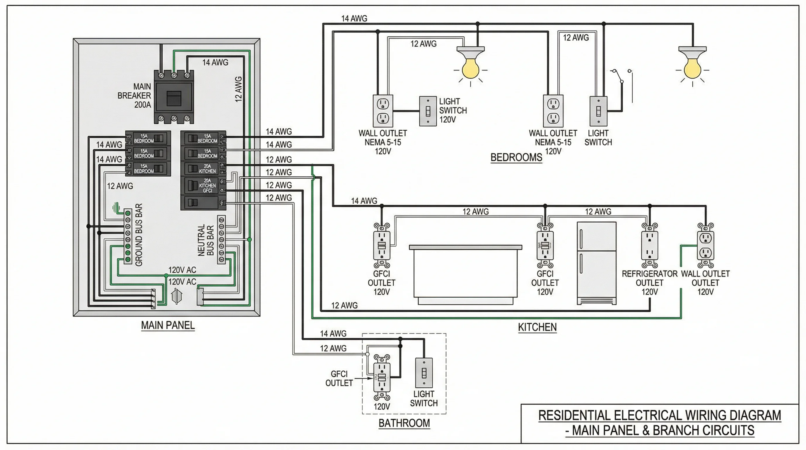 Physics
Wiring Diagram Maker
Wiring diagrams for home, automotive, appliance, and industrial systems from a plain-English description.
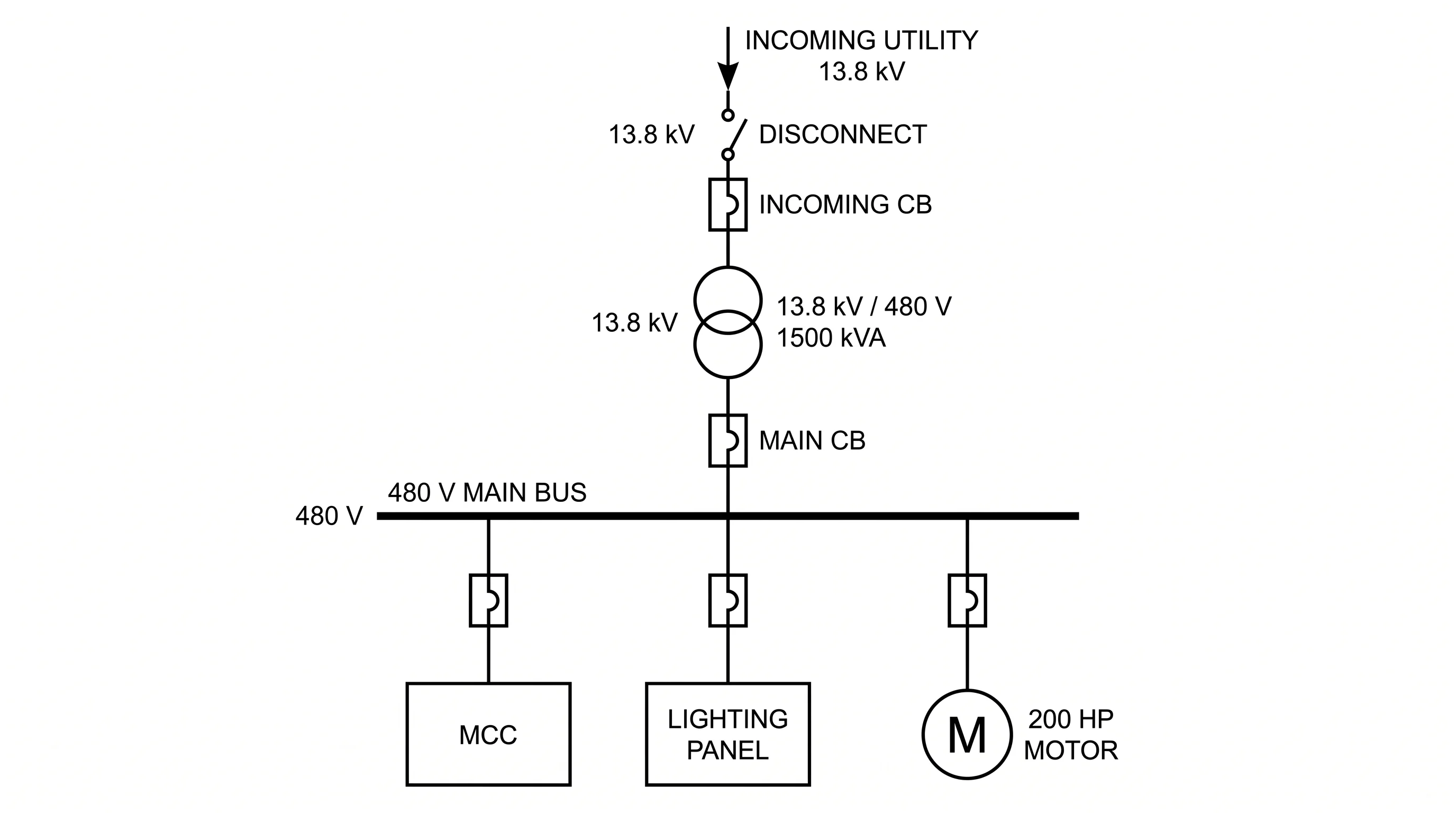 Engineering
Single-Line Diagram Generator
Facility-level one-line diagrams of sources, transformers, and feeders.
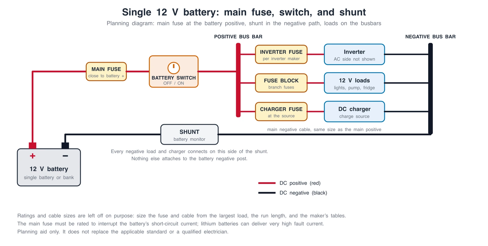 Engineering
Battery Wiring Diagram Generator
Generate battery wiring diagrams: main fuse, switch, shunt, series or parallel banks, and DC-DC charging, with exact reference diagrams.
 Engineering
Control Panel Wiring Diagram Generator
Generate control panel wiring diagrams: DOL motor starters, PLC 24V DC inputs and outputs, and panel layouts, with an exact ladder diagram.