GFCI Outlet Wiring Diagram Generator LINE vs LOAD, Brass and Silver
Exact GFCI outlet wiring diagrams: LINE only, or LINE and LOAD with protected receptacles after it. Brass hot, silver neutral, green ground.
GFCI Outlet Wiring Diagrams
Exact diagrams drawn in code from reviewed scenes. Each shows the panel, the GFCI receptacle, the cables and the screw each conductor lands on. Click a diagram to open it full size.
One cable in the box: LINE terminals only
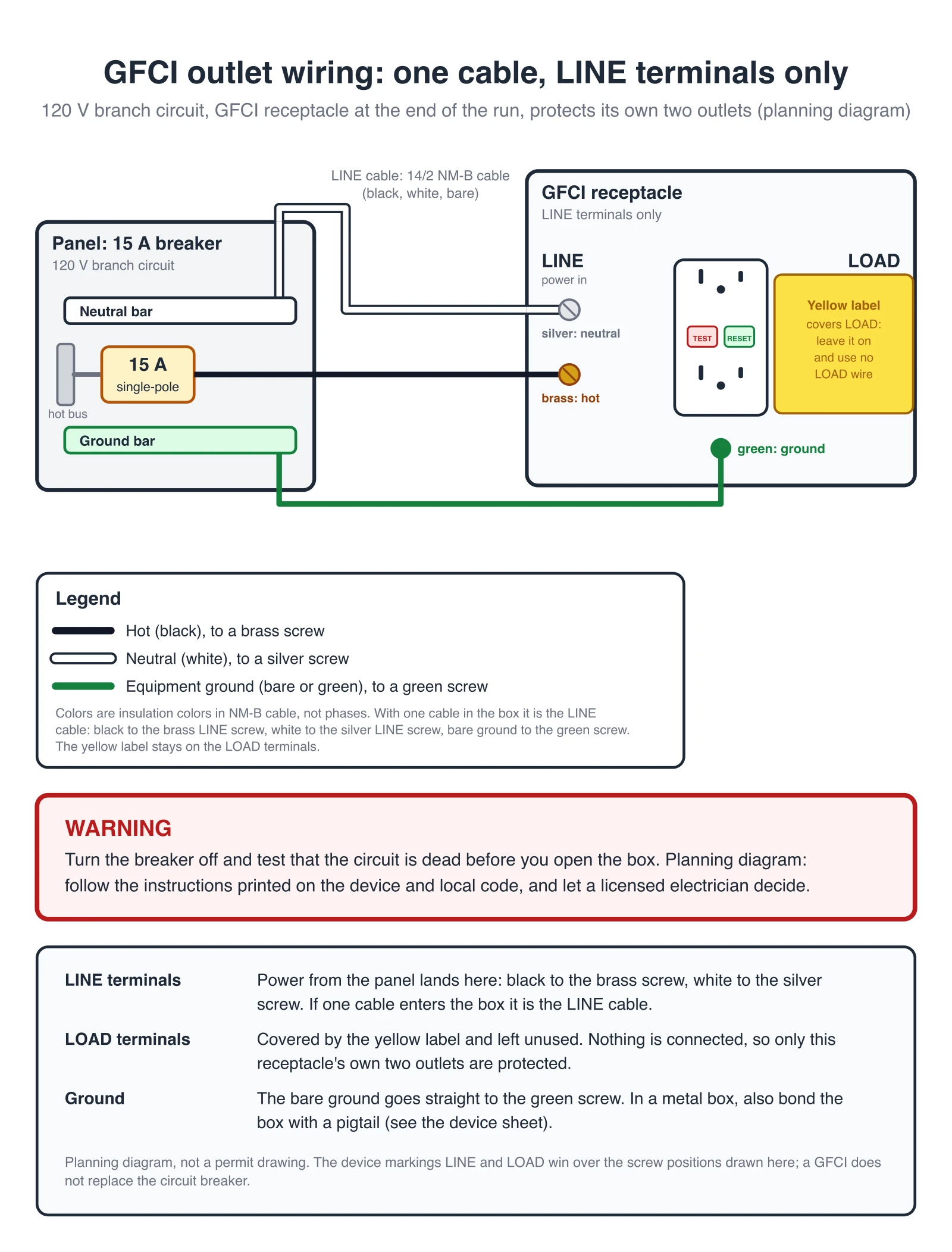
The most common case: one cable enters the box (the sample is 14/2 on a 15 A circuit; use the wire size and device rating that match your breaker), so it is the LINE cable. Black goes to the brass LINE screw, white to the silver LINE screw and the bare ground to the green screw. The yellow label stays on the LOAD terminals. The GFCI then protects its own two outlets only.
LINE and LOAD: one protected receptacle after the GFCI
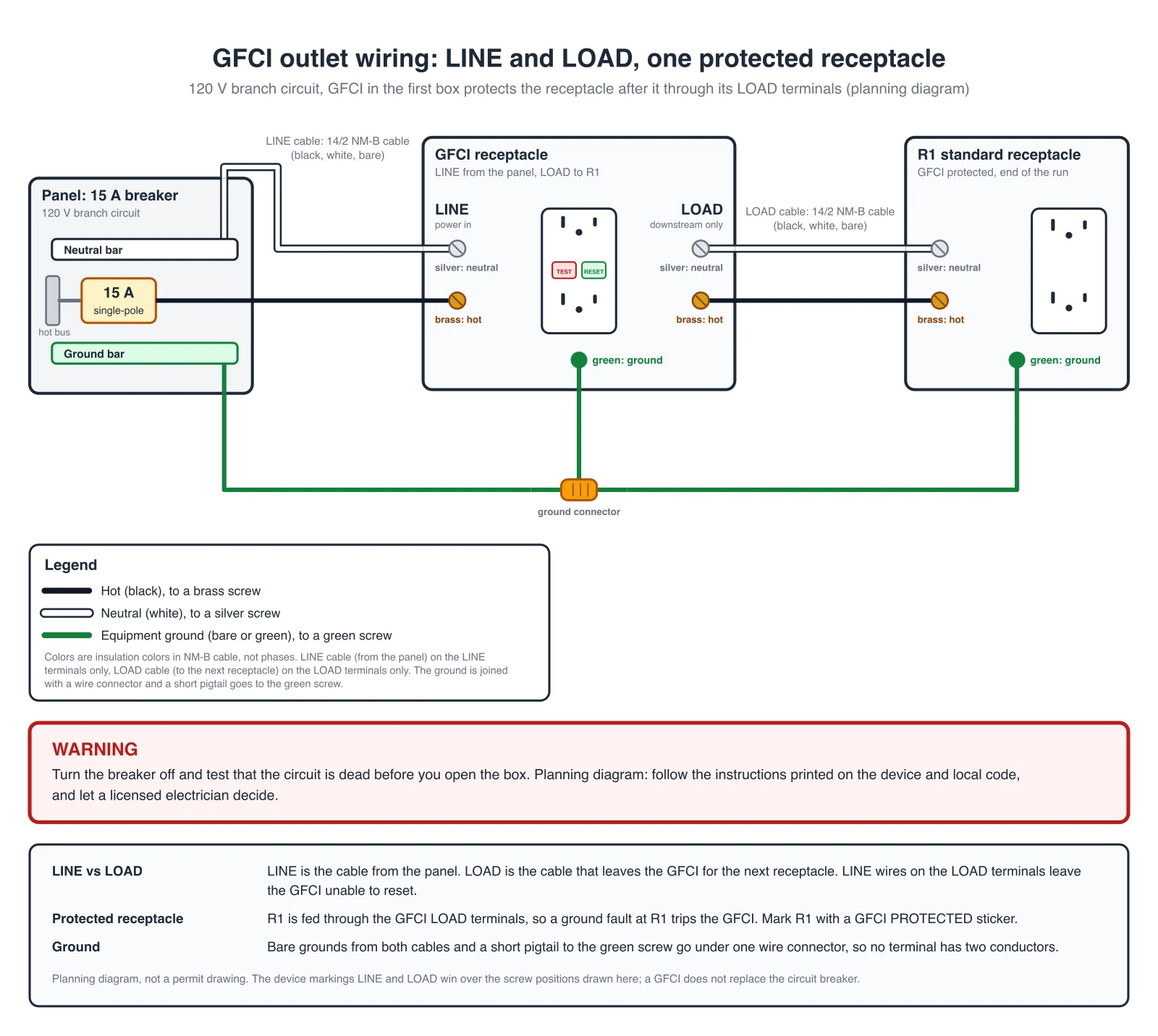
Two cables enter the GFCI box. The cable from the panel goes to the LINE terminals, the cable that leaves for the next receptacle goes to the LOAD terminals, and nothing else is on either pair. The grounds of both cables and a short pigtail to the green screw share one wire connector, so no screw carries two conductors.
LINE and LOAD: two protected receptacles after the GFCI
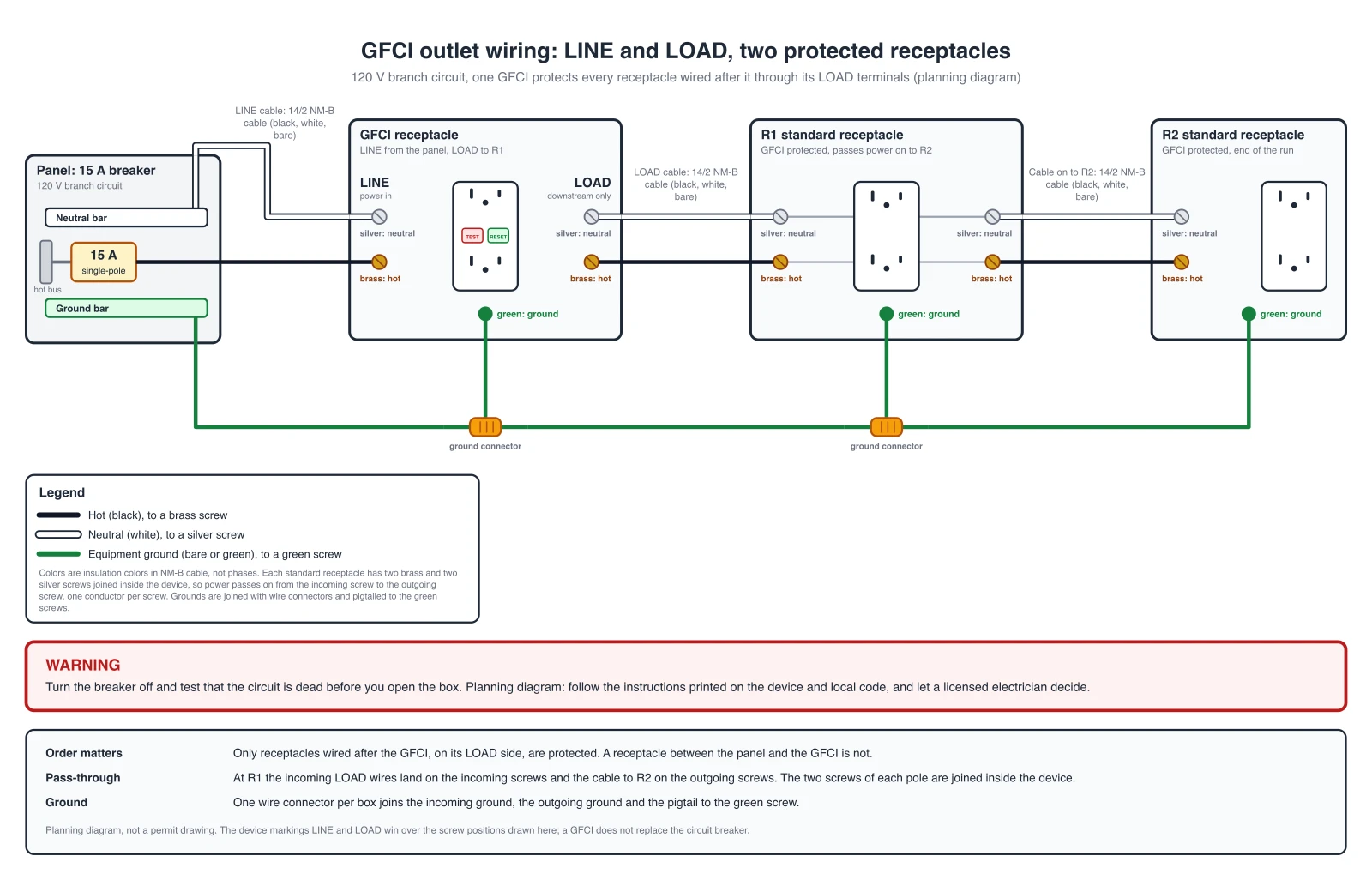
The same GFCI feeding a run of receptacles. At the first receptacle the incoming cable lands on the incoming screws and the cable to the second receptacle on the outgoing screws, which are joined inside the device on most standard receptacles. Every receptacle after the GFCI on its LOAD side is protected. A receptacle between the panel and the GFCI would not be.
GFCI Terminal Table: What Goes Where
The same rules the checker applies to every diagram above.
| Terminal | Screw colour | Conductor | Comes from |
|---|---|---|---|
| LINE hot | brass | Hot (black) | The cable from the panel |
| LINE neutral | silver | Neutral (white) | The cable from the panel |
| LOAD hot | brass | Hot (black) | The cable to the next receptacle, only if one is used |
| LOAD neutral | silver | Neutral (white) | The cable to the next receptacle, only if one is used |
| Ground | green | Ground (bare or green) | Ground wires joined by a wire connector, pigtail to the screw |
One conductor per screw. Screw positions differ between makers, so the LINE and LOAD markings on the device win over the drawn positions.
This page covers the receptacle only. For other circuits, such as home, automotive or appliance wiring, use the Wiring Diagram Maker. For a generator hookup, see the Generator Transfer Switch Wiring Diagram Builder.
AI illustration of your outlet wiring
Describe a GFCI hookup to get a quick picture. AI images can swap LINE and LOAD or put two wires on one screw, so use the exact diagrams and the table above for the real connections and check every screw of an AI picture.
Generate an AI GFCI Wiring Illustration
Example: Exact reference for this connection (drawn in code, not the AI output)View full sizePreview is free on this page ·
Your GFCI outlet wiring diagram will appear here
AI diagrams are drafts. Check LINE and LOAD, every screw colour and every ground against the device markings.
Source (checked October 2026): Leviton, Installing and Testing a GFCI Receptacle, instruction sheet PK-93755-10-00-2A (copy hosted by US Electrical Services). The LINE and LOAD rules, the screw colours, the ground connector, the yellow label, the box limits, copper-only wire and the test procedure above follow this one manufacturer's sheet. Other makers use the same LINE and LOAD idea, but screw positions, box limits and test steps differ, so read the sheet packed with your device. Where GFCI protection is required depends on the electrical code in your area.
What a GFCI outlet wiring diagram shows
A GFCI outlet wiring diagram shows which conductor lands on which screw of a ground-fault circuit-interrupter receptacle. A GFCI receptacle has two pairs of terminals. The LINE pair takes the cable that brings power from the panel. The LOAD pair is only for a cable that carries protected power on to other receptacles. On each pair the brass screw is the hot terminal and the silver screw is the neutral (white) terminal, and a green screw takes the ground. The diagrams above are drawn in code from reviewed scenes, so each screw carries the conductor the device instructions name for it.
LINE vs LOAD: what the two pairs of terminals do
- The LINE cable delivers power from the service panel to the GFCI. The device instructions say to connect it to the LINE terminals only. If only one cable enters the box, it is the LINE cable.
- The LOAD cable delivers power from the GFCI to another receptacle in the circuit and goes to the LOAD terminals only. The LOAD terminals sit under a yellow label on a new device, and the label stays on until you have a LOAD cable to connect.
- The LOAD side is fed through the GFCI, so a ground fault on a protected receptacle trips the GFCI. That is how one GFCI protects a whole run. Put the GFCI first in the run: receptacles between the panel and the GFCI are not protected.
- The screw colours are the same on both pairs: brass is hot, silver is the white neutral. The positions of the screws differ between makers, so the LINE and LOAD markings printed on the device win over any drawing, including these.
How to tell the LINE cable from the LOAD cable
- With one cable in the box there is nothing to decide: it is the LINE cable.
- With two cables, the device instruction sheet gives a procedure: separate the hot and white wires of one cable, cap each one on its own, restore power, and see whether the old receptacle is live. If it is, the capped wires are the LOAD wires. If it is not, they are the LINE wires. Then turn the power off again, label both cables and remove the receptacle.
- This procedure needs live power with bare conductors capped in the box. If you are not trained to do that safely, have an electrician identify the cables. Do not tell LINE from LOAD by conductor colour alone: both cables look the same.
Why the ground uses a wire connector and a pigtail
A GFCI box often holds the ground of the incoming cable, the ground of the outgoing cable and the green screw of the device. The device instruction sheet joins the ground wires with a wire connector and runs a short bare or green wire from the connector to the green screw, and also to the box if the box has a grounding terminal. A pigtail means each screw carries one conductor, and the other grounds stay connected even when the device is removed. With one cable and a box with no grounding terminal, the sheet connects the bare ground directly to the green screw, as in the first diagram.
Common GFCI wiring mistakes
- LINE and LOAD swapped. The cable from the panel on the LOAD terminals leaves the GFCI unable to reset and without power to its face or to any receptacle fed from it. The checker behind these diagrams rejects this drawing.
- Hot on the silver screw or neutral on the brass screw. The silver screw is for white conductors and the brass screw for hot conductors. The checker rejects a diagram that crosses them.
- Two conductors on one screw. This is why the ground is pigtailed. The checker rejects a diagram with two conductors on one terminal of the GFCI or a receptacle.
- A receptacle you expect to be protected but wired before the GFCI. Only the receptacles on the LOAD side are protected, so test them (see below).
- Aluminum wire. The sheet says to use the GFCI with copper or copper-clad wire only, not with aluminum wire.
- Damp or wet locations. For a wet location the sheet says to protect the GFCI with a weatherproof cover that keeps both the receptacle and any plugs dry, such as an in-use cover.
- Wiring a box that is too full. The device sheet says not to install the GFCI in a box that has more than four wires (not counting grounds), or cables with more than two wires (not counting the ground). In that case call an electrician.
Test the GFCI and mark the receptacles it protects
- A new GFCI ships in the tripped condition and cannot be reset until it is wired correctly and has power. Plug a lamp or radio into the GFCI and leave it plugged in, then turn the power on. Press TEST first. If the indicator light is on and the lamp is off, LINE and LOAD are reversed and RESET will not work: turn the power off and check the wires against the diagram. Otherwise press RESET fully. If the lamp and the indicator light come on, the GFCI is installed correctly.
- If you used the LOAD terminals, press TEST and plug a lamp into the other receptacles to see which ones lose power. Those are protected. Put a "GFCI PROTECTED OUTLET" sticker on every receptacle that lost power, and do not plug life-saving devices into them. The sheet says not to install a GFCI on a circuit that powers life support equipment, because a trip shuts the equipment down.
- Press TEST and then RESET every month. If the indicator light does not go out and come back, or the GFCI cannot be reset, replace it.
Exact diagrams vs AI drafts
The three diagrams above are exact diagrams. They are drawn in code from reviewed netlists, and a checker compares every drawing with a reference table: the LINE terminals are fed from the panel, the LOAD terminals only feed downstream receptacles, brass takes hot, silver takes neutral, green takes ground, and no terminal carries two conductors. The checker also rejects deliberately wrong drawings, such as swapped LINE and LOAD or a neutral on the brass screw. We do not show AI-generated wiring images as examples, because image models often swap LINE and LOAD or put two wires on one screw. The generator on this page still produces an AI illustration from your prompt. Treat it as a rough picture, compare it with the exact diagrams and with the markings on your device, and let a licensed electrician decide what is installed. A diagram from this page is a planning picture. It is not an installation drawing and it does not replace the device instructions or the electrical code in your area.
Frequently Asked Questions
Related Engineering Tools
 Engineering
Wiring Diagram Maker
Wiring diagrams for home, automotive, appliance, and industrial systems from a plain-English description.
 Engineering
Three Phase Motor Wiring Diagram Generator
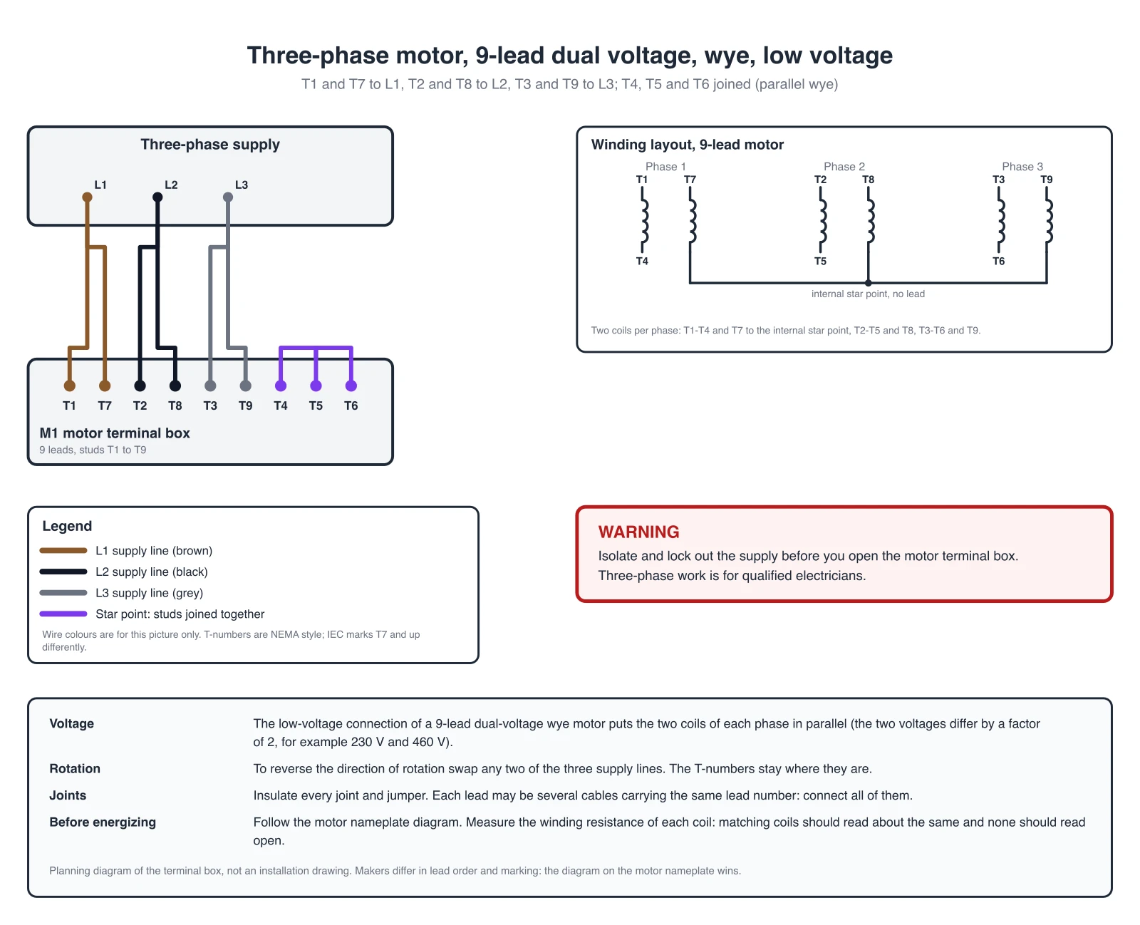
Exact terminal diagrams for 3, 6, 9 and 12 lead motors in wye and delta.
 Engineering
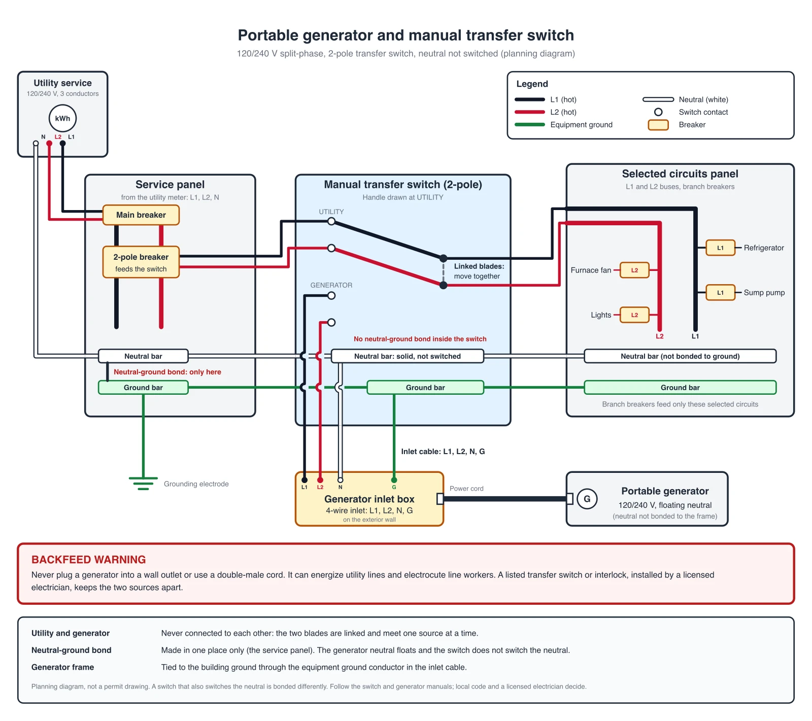
Generator Transfer Switch Wiring Diagram Builder
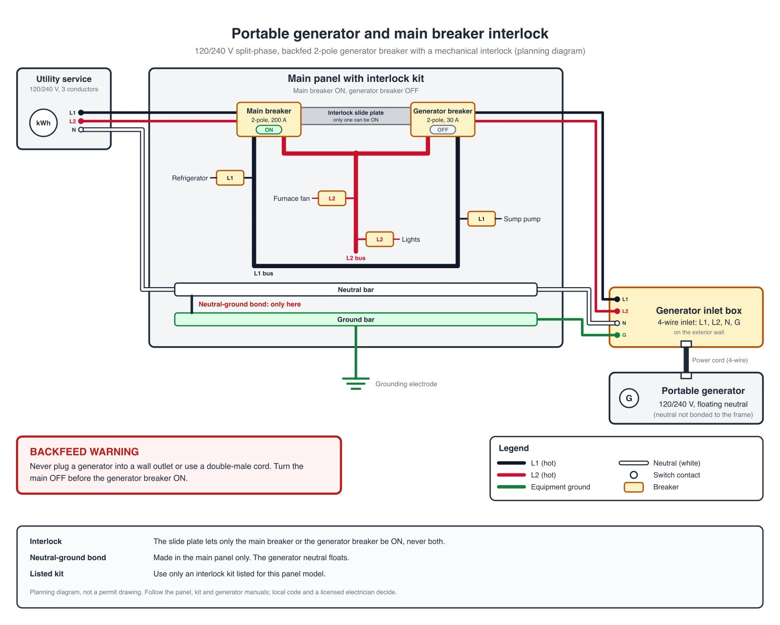
Manual switch, interlock kit and ATS hookups with exact reference diagrams.
 Engineering
Control Panel Wiring Diagram Generator
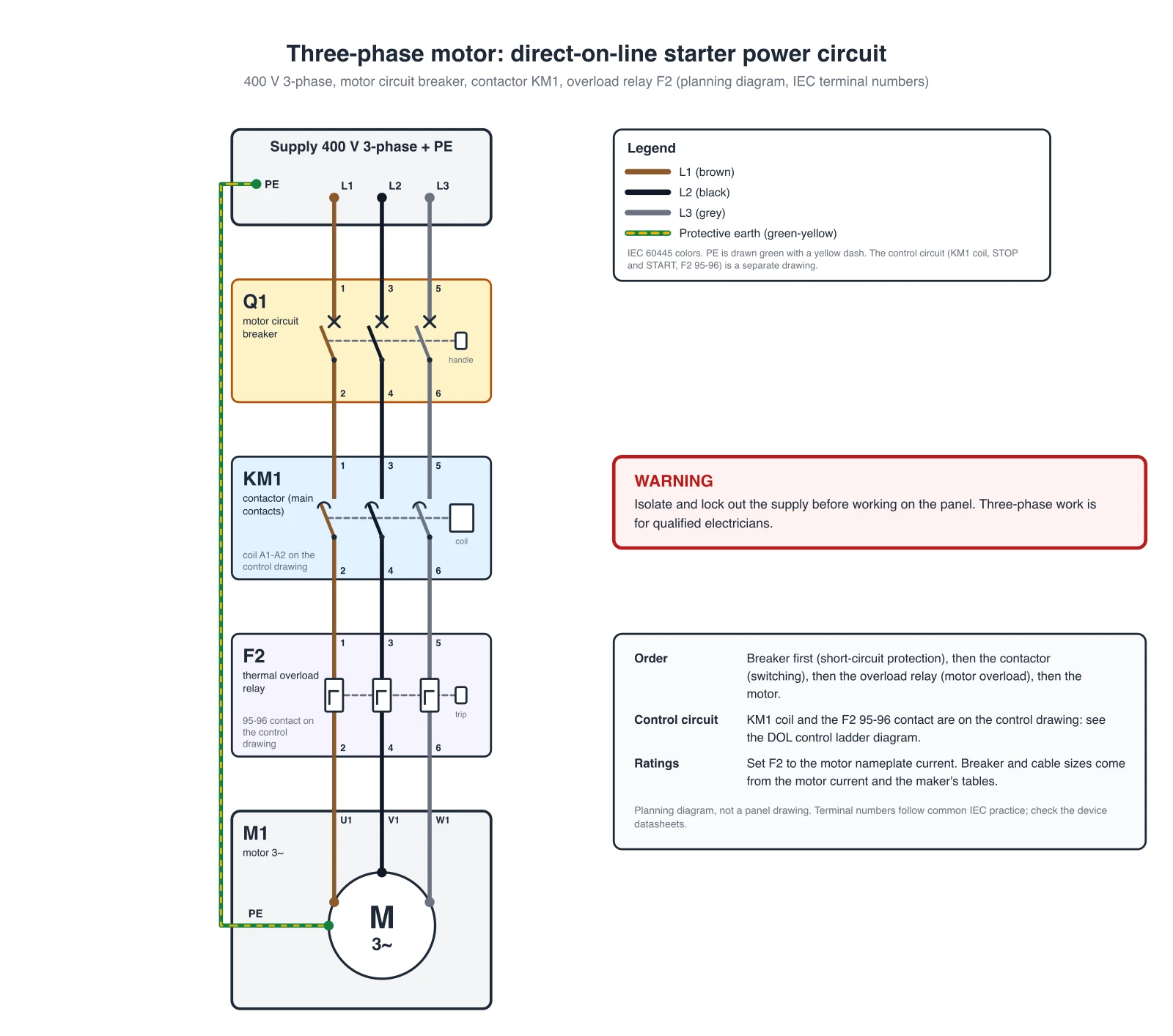
Direct-on-line motor starter power circuit and start/stop ladder diagram, PLC I/O and panel layouts.