Boat Wiring Diagram Generator for 12V Boat Electrical
Generate a boat wiring diagram from a text prompt: single or dual battery, battery switch, fuse block, bilge pump, outboard. With exact reference diagrams.
Create Your Boat Wiring Diagram
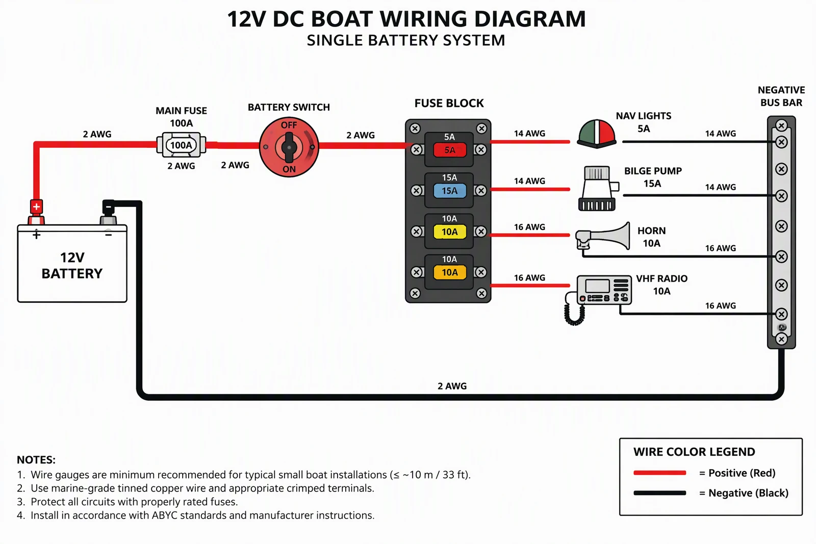 Example: Single battery with fuse blockView full size
Preview is free on this page ·
Your boat wiring diagram will appear here
AI diagrams are drafts. Check every connection, fuse, and polarity before use.
Boat Wiring Diagram Examples
Two exact reference diagrams drawn in code, plus one AI diagram with its known flaws noted. AI diagrams need human review.
Single battery 12V system (exact diagram)
Drawn in code, not by AI. Battery positive goes through the main fuse, then the battery switch, then the fuse block. The bilge pump takes its own fused feed ahead of the switch so it still runs with the switch off. Every load returns to the negative bus bar. Gauges are illustrative.
Dual battery with a 1-2-BOTH-OFF switch (exact diagram)
Drawn in code. Each battery has its own fuse at the positive terminal and feeds one input of the selector switch. The common output feeds the starter and the house fuse block, and the alternator charges back through the same switch. Both batteries share one negative bus bar. In a real install, the alternator output and the house fuse panel feed would each need their own overcurrent protection.
Single battery with fuse block (AI diagram)
AI-generated from a text prompt. Labels, colors, and the negative return are right. This is the kind of draft you must correct before use. Known flaws: the fuse block shows one input wire to the top fuse only, with the shared bus implied; fuse ratings are printed twice in each slot; the fuse colors do not follow standard blade-fuse colors; the generated notes are invented guidance; and the bilge pump is on the switched feed, so it stops when the switch is off.
For wiring diagrams outside boats, use the Wiring Diagram Maker. To compare tools, read 12 best wiring diagram software and apps, and for drawing conventions see how to make a wiring diagram.
What a boat wiring diagram shows
A boat wiring diagram shows how the boat’s 12V DC system is connected: where power starts at the battery, what protects it, what switches it, and how every load returns to the negative side. Most small-boat diagrams cover the same few blocks: battery or batteries, a battery switch, a main fuse or breaker, a fuse block or breaker panel, the loads (navigation lights, bilge pump, horn, VHF radio, electronics), and a negative bus bar. Describe your boat in the prompt box, generate a draft, and compare it with the exact reference diagrams in the gallery above.
Single battery system: the order of parts
- Battery positive goes first to overcurrent protection, a fuse or breaker, close to the battery. ABYC E-11 sets a distance limit for this; check the current edition for the exact figure and exceptions.
- Next comes the battery switch, which lets you cut power to the boat’s circuits when you leave it.
- The fuse block or breaker panel splits power into branch circuits, each with a fuse or breaker sized for the wire and the load.
- Every load returns on its own negative wire to the negative bus bar, and one main negative cable ties the bus bar back to the battery negative.
- Always-on loads such as an automatic bilge pump are commonly given their own fused feed ahead of the switch, so they keep working when the switch is off. The exact diagram above draws it that way.
Dual battery systems and the 1-2-BOTH-OFF switch
- A dual battery setup keeps one battery for starting the engine and a second for the house loads, so a flat house battery does not strand you.
- Each battery gets its own fuse at the positive terminal and feeds one input of the selector switch. In the diagram on this page, position 1 uses the start battery and 2 uses the house battery (switch numbering varies by maker). BOTH connects them in parallel, and OFF disconnects both.
- The common output of the switch feeds the starter and the house fuse block, and the alternator charges whichever battery is selected through the same switch.
- Do not switch to OFF with the engine running: an alternator with no battery to charge can be damaged. Use BOTH for emergency starts and return to a single battery afterwards.
- A charge combiner (also called an automatic charging relay) or an isolator is a common alternative to leaving the switch on BOTH. The exact diagram leaves it out for clarity.
Wire color, gauge, and voltage drop
On boats, DC positive is conventionally red and DC negative is black or yellow (ABYC E-11). Gauge depends on the current the circuit carries and the length of the round trip, not just the load: the longer the run, the heavier the wire. Common guidance limits voltage drop to 3% for critical circuits such as navigation lights and electronics and 10% for non-critical ones such as cabin lights. Use marine-grade stranded tinned copper wire and size from the standard’s tables, not from a gauge printed on a generated picture. The gauges in the diagrams on this page are illustrative.
Outboard boats: starting and charging
An outboard adds two things to the diagram: the starter circuit and the charging circuit. The starter cable is short and heavy and runs from the battery positive to the starter. The engine’s charging coil feeds a rectifier or regulator, which charges the battery. Outboard makers publish their own harness diagrams, and those are the reference for the engine side; use a generated diagram for the boat side: battery, switch, fuse block, bilge pump, and lights.
How to generate a boat wiring diagram from text
- List the parts you actually have: battery or batteries, battery switch, main fuse, fuse block, each load with its rating.
- State the order of the power path, and say where the negative returns go.
- Ask for red positive wires, black negative wires, a gauge label on every wire, and a color legend.
- Ask for generic components, no brand names, and short English labels.
- Generate, then check every connection against your own boat. Re-prompt to fix anything that is wrong.
Exact diagrams vs AI illustration on this page
The two exact diagrams are drawn in code, so every wire and label is placed on purpose. The AI diagram was generated from the prompt shown. We checked it for polarity, fuse and switch position, wire colors, and label spelling, and its caption lists the flaws we found. Two other AI attempts at dual battery and outboard systems were left out because their wiring was unsafe or misleading, such as a fuse rated far above its wire and a bypassed battery switch. AI output is useful for a quick layout draft, but it can leave out a connection, put a fuse in the wrong place, or draw a switch that is not in the circuit. A diagram from this page is a planning sketch. It is not a traced schematic or a wire list, and it does not replace ABYC guidance or a certified marine electrician. This page covers 12V DC only. AC shore power, bonding, and ignition-protection requirements for gasoline engine spaces are separate and need ABYC guidance or a certified marine electrician.
Frequently Asked Questions
Related Engineering Tools
 Physics
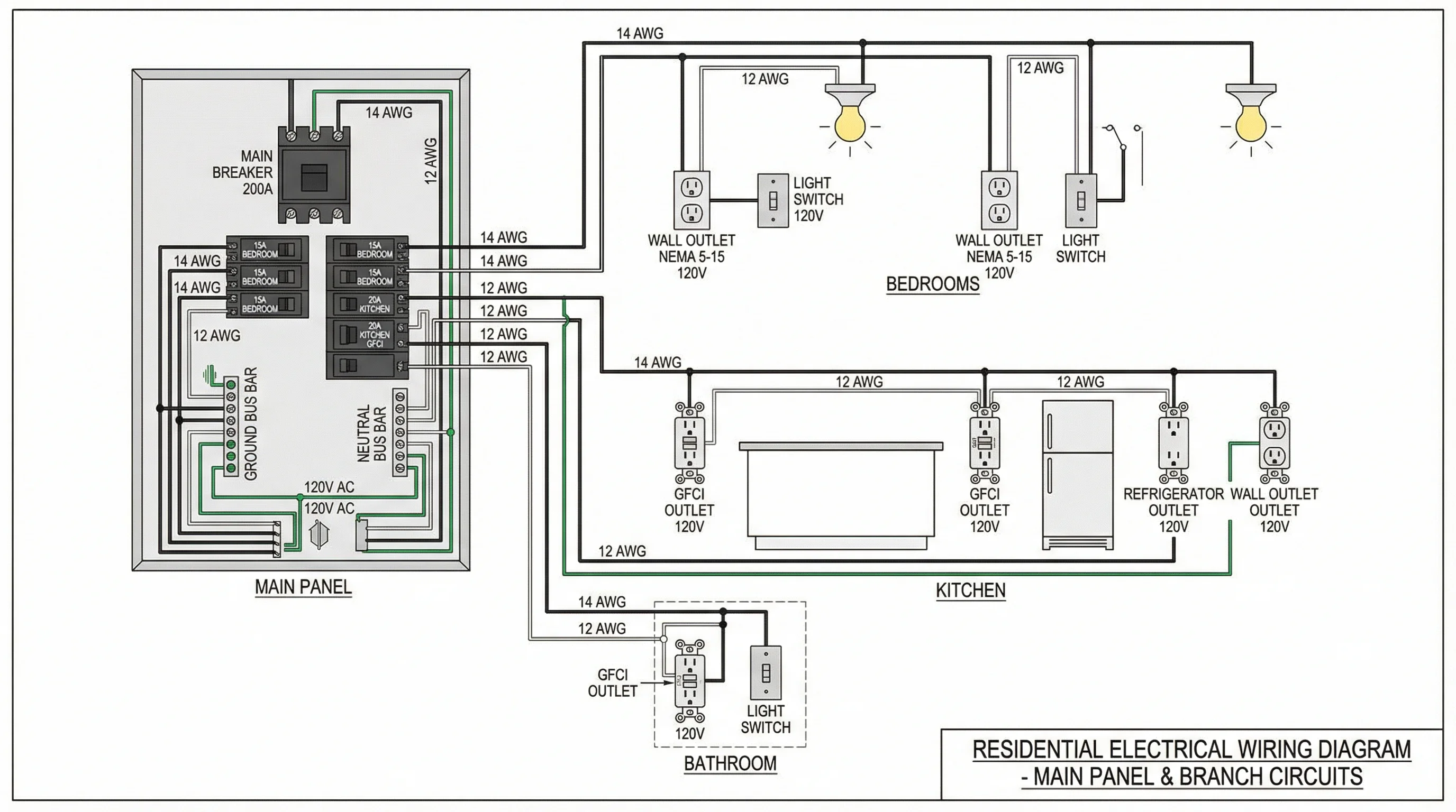
Wiring Diagram Maker
Wiring diagrams for home, automotive, appliance, and industrial systems from a plain-English description.
 Physics
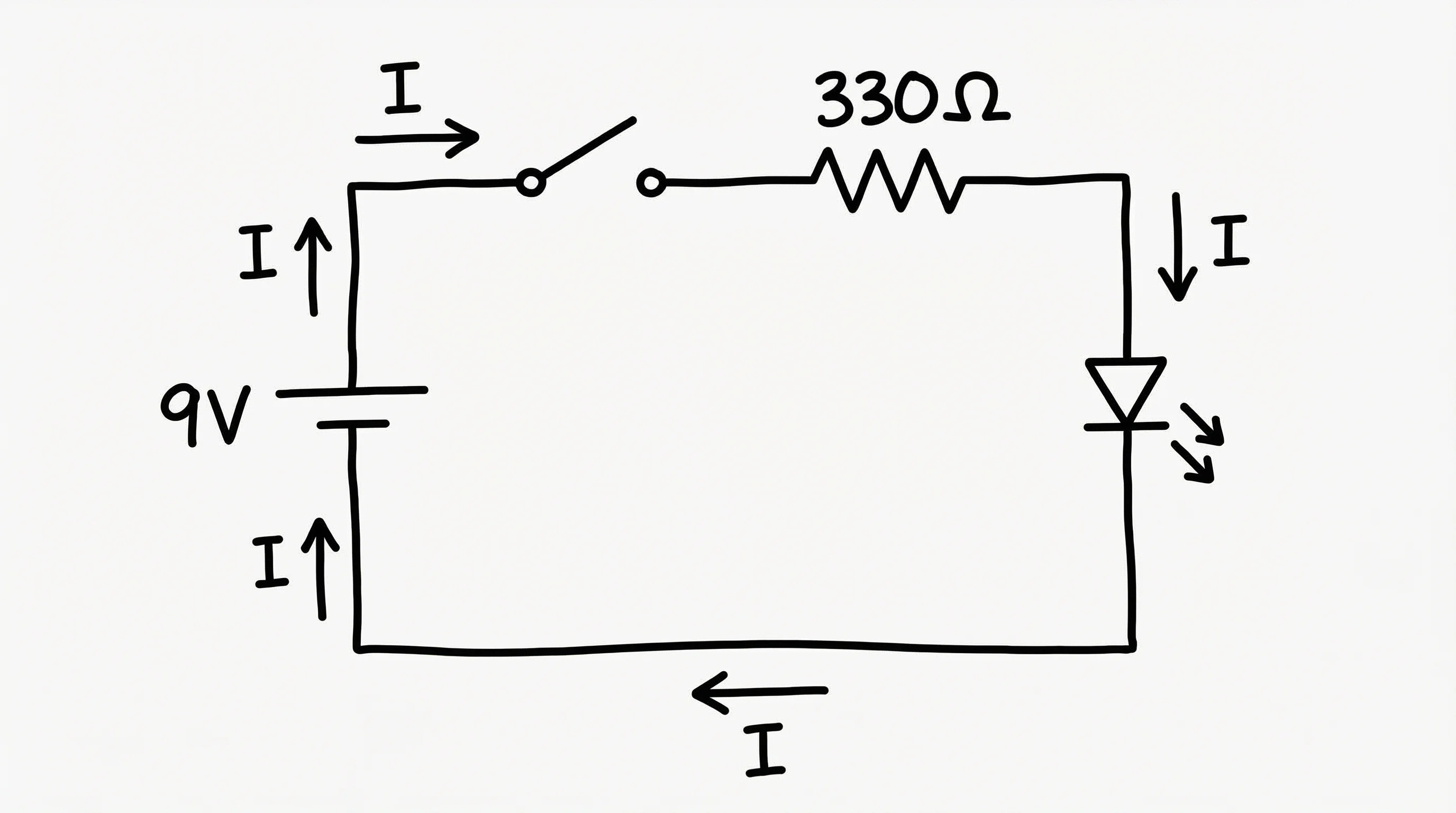
Circuit Diagram Maker
Draw circuit schematics with resistors, capacitors, batteries, and switches.
 Engineering
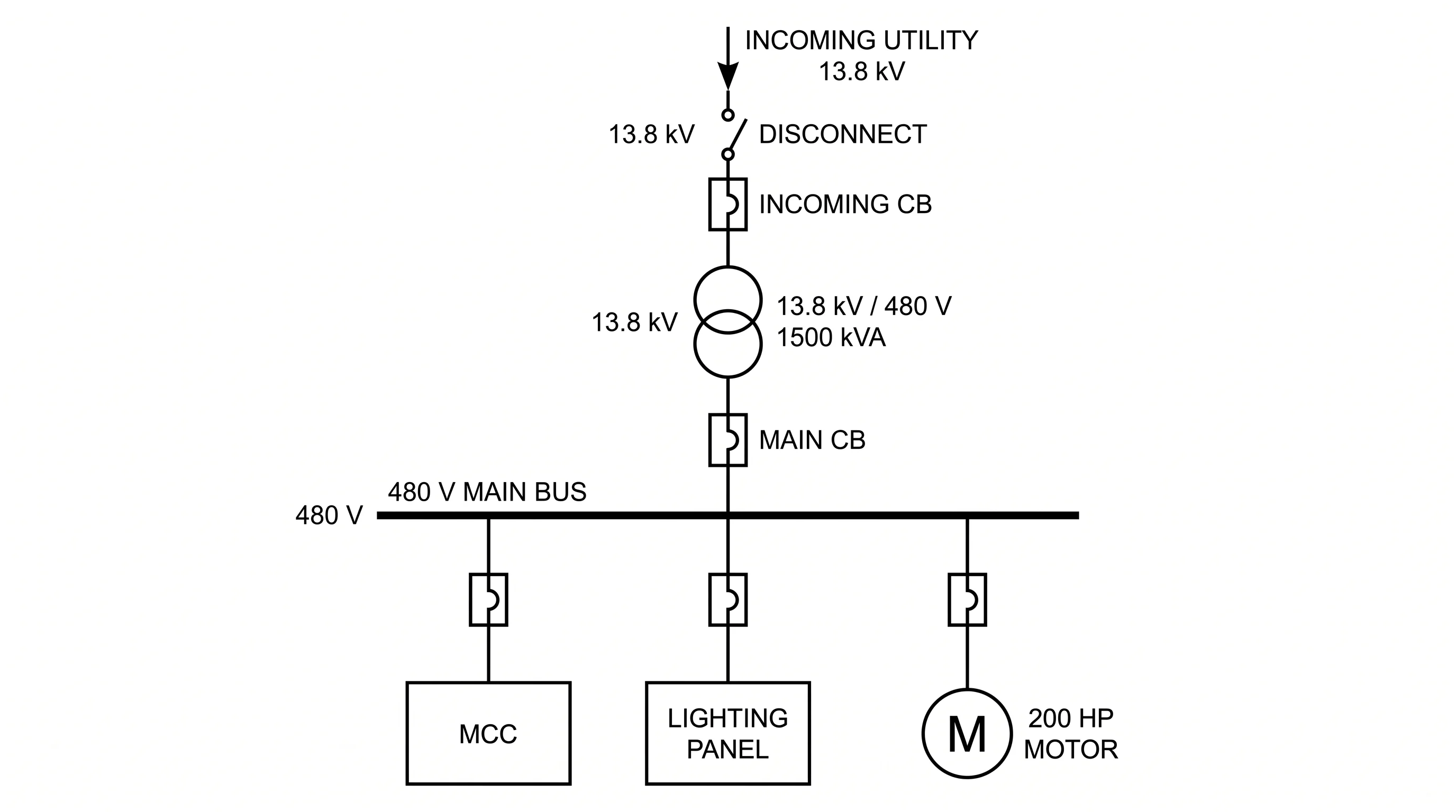
Single-Line Diagram Generator
Facility-level one-line diagrams of sources, transformers, and feeders.
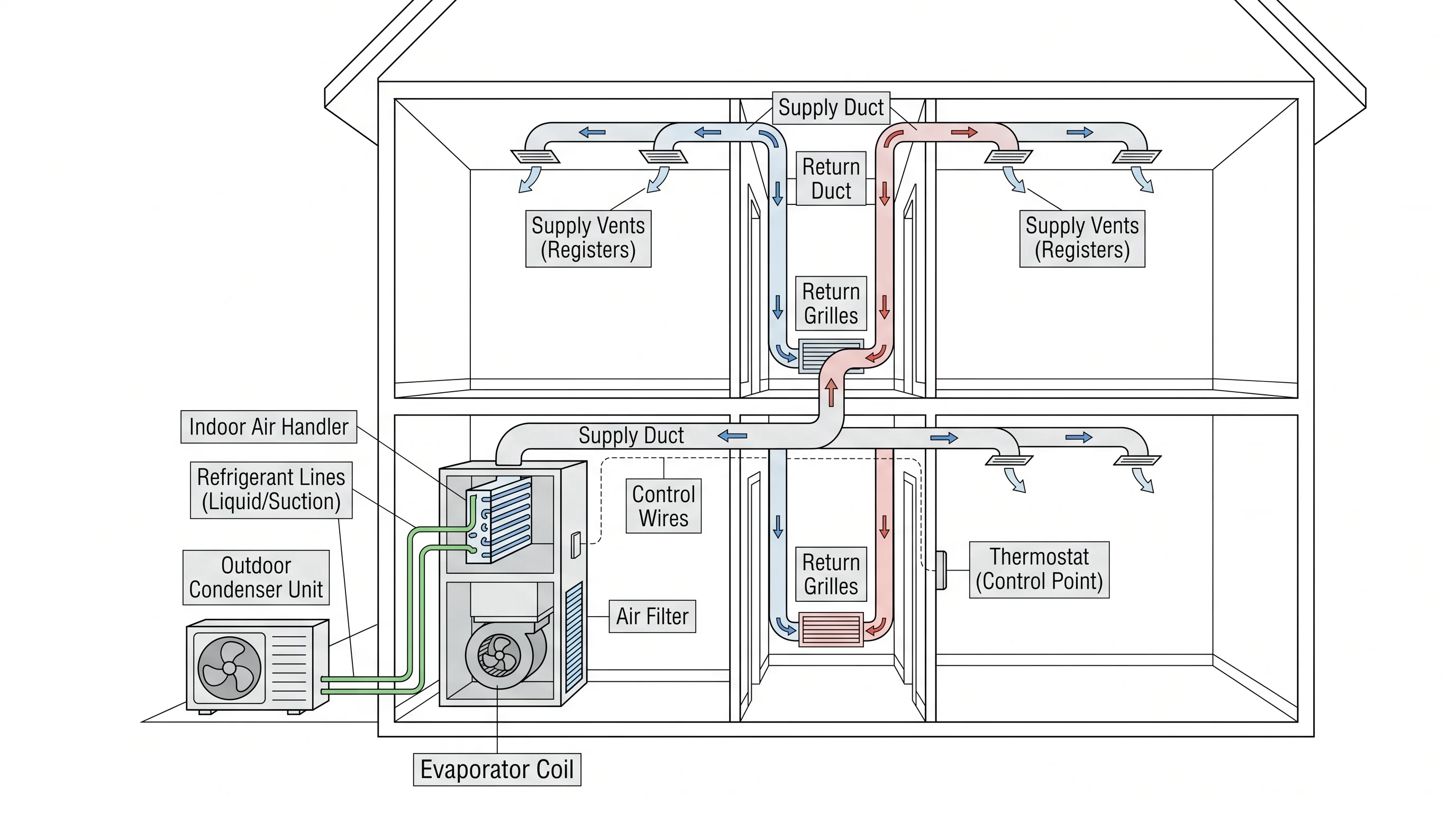 Engineering
HVAC Diagram Generator
HVAC system, refrigerant-cycle, and airflow diagrams for class, bids, or service notes.