Relay Wiring Diagram: 4-Pin and 5-Pin Guide
Read 4-pin and 5-pin relay wiring diagrams: identify 85, 86, 30, 87 and 87a, compare contact states, and check coil polarity with precise illustrated examples.
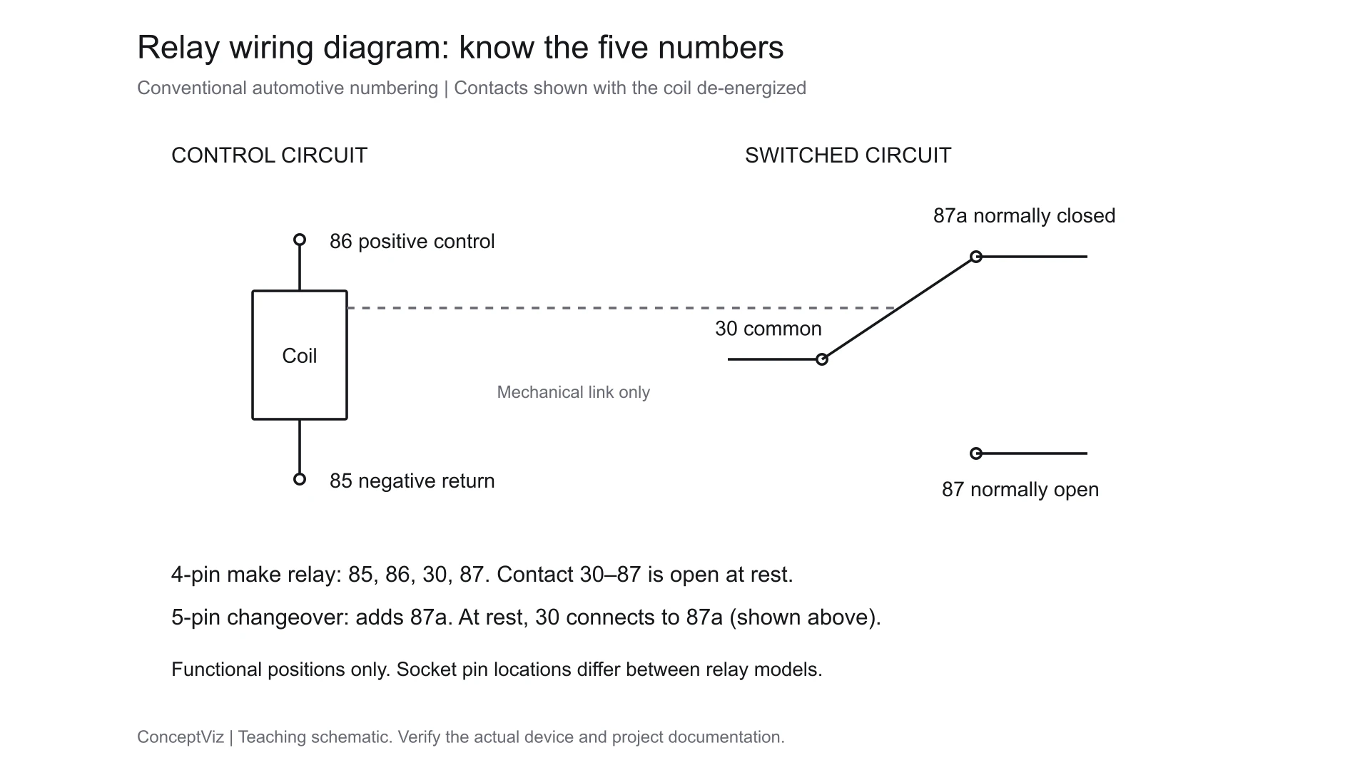
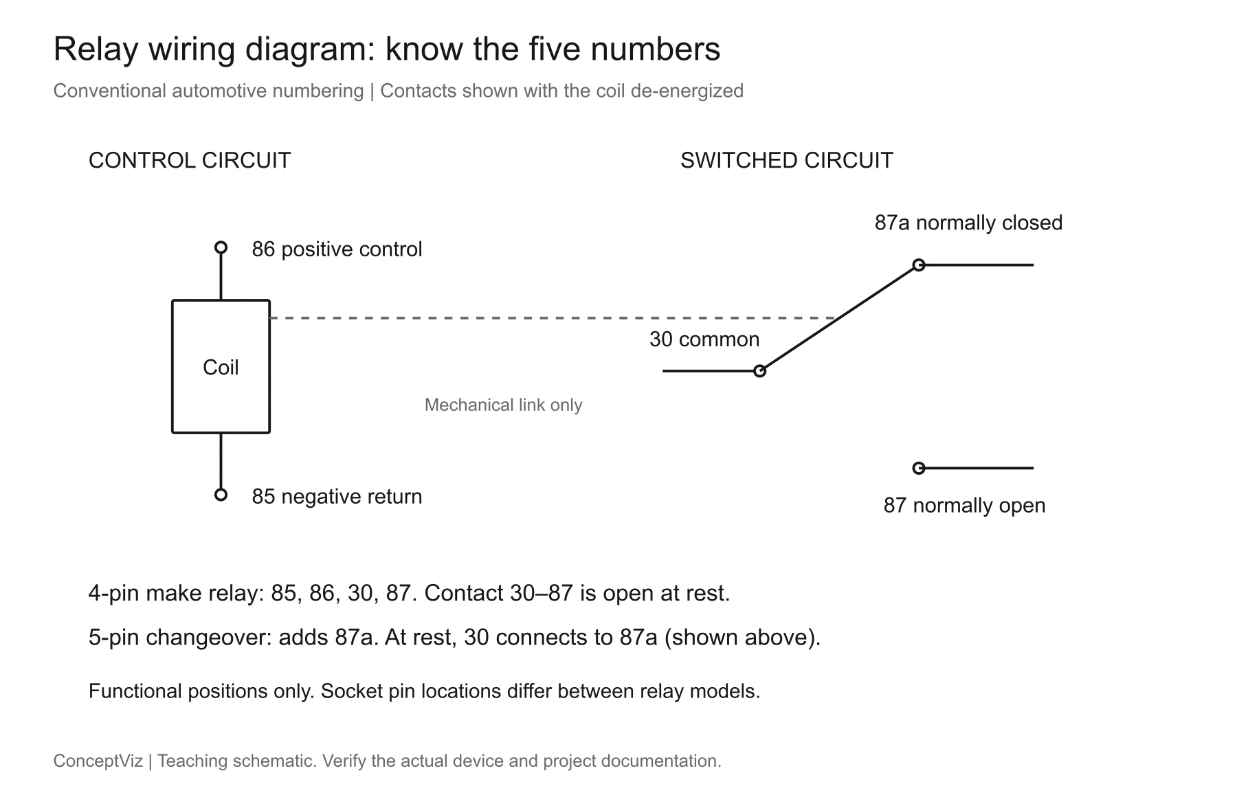
In the conventional automotive relay numbering used here, 85 and 86 are the coil terminals, 30 is the switched common, 87 is the normally open output, and 87a is the normally closed output on a changeover relay. A four-pin make relay closes 30 to 87 when its coil is energized. A five-pin changeover relay moves 30 from 87a to 87.
Those numbers describe electrical functions, not a universal arrangement of blades on the underside. Check the circuit printed on the actual relay and its part-specific datasheet before matching it to a socket. This guide uses precise teaching diagrams for conventional electromechanical automotive relays. It does not cover solid-state relays, mains installations or every vehicle control module.
Wiring Diagram Maker
Draft a labeled connection diagram from your circuit description, then check every terminal against the actual relay and vehicle documentation.
Draft a wiring diagram →Start with the pin numbers
| Terminal | Function in this guide | What to check |
|---|---|---|
| 85 | Coil negative / return | Polarity marking and suppression components |
| 86 | Coil positive / control input | Rated coil voltage and the control circuit |
| 30 | Common contact; supply input in these examples | Correct source and protection for the load circuit |
| 87 | Normally open, or make, contact | Connected to 30 when the coil is energized |
| 87a | Normally closed, or break, contact | Connected to 30 when the coil is de-energized |
HELLA's relay catalog gives these terminal functions and explains make and changeover operation. It also identifies suppression resistors and diodes placed in parallel with some relay coils. The pin descriptions above follow that manufacturer's convention, checked October 10, 2026. HELLA electromechanical relay catalog, pages 9–11.
Original teaching schematic, shown with the coil off. The dashed line indicates mechanical actuation, not an electrical wire. It is a function map, not a socket footprint. Open the editable SVG.
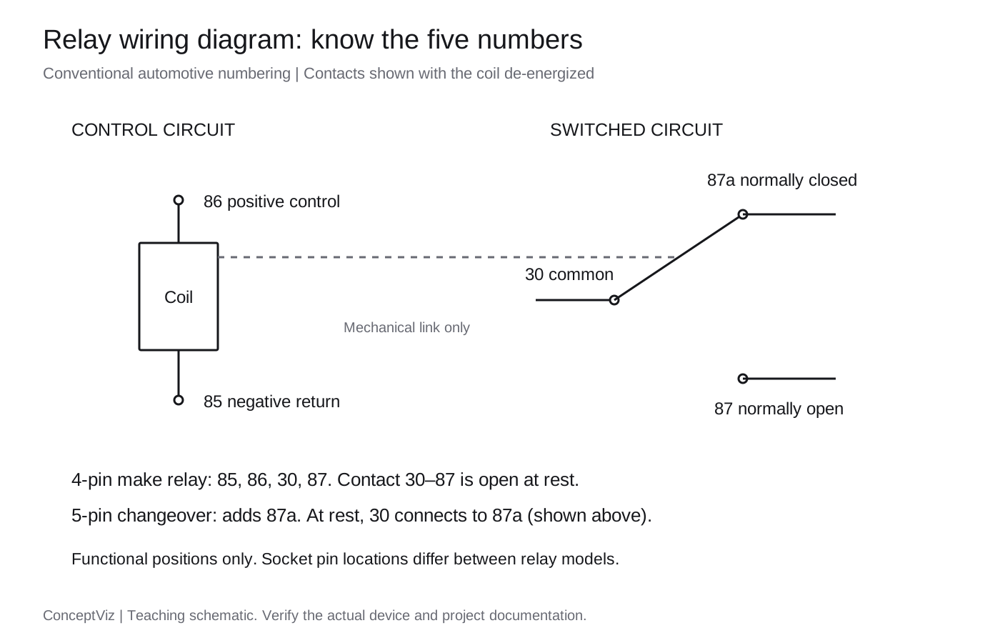
“Normally” means the coil is not energized. It does not mean the most common state while a vehicle is running, and it does not mean “safe.” A normally closed output can carry power while the control switch is off. Label the coil state beside each diagram so that a reader does not have to infer it from a switch elsewhere on the page.
Why the coil and load circuit are separate
An electromechanical relay uses a magnetic coil to move contacts. The control circuit supplies the coil; the contact circuit switches the load. In the basic relay mechanism, these are electrically separate. A dashed mechanical link in a schematic connects the ideas, not the conductors.
A vehicle can connect both circuits to the same battery and return system outside the relay. That shared external supply does not turn the coil into a conductor between 30 and 87. In a teaching drawing, trace the control loop and load loop separately. You should be able to explain how the coil is energized without sending the load current through the control switch.
A relay also does not create extra power. The load still needs a suitable source, conductors, connections and protection. The relay's contact rating and its coil voltage describe different properties. A “12 V” coil marking is not a wire-size instruction, and a contact-current marking is not permission to use that number as the fuse size for every load.
Read a 4-pin relay wiring diagram
The following example shows a conventional normally open relay with a positive-side control switch. Both loops return to the battery negative system. F1 and F2 identify protection for the two illustrated supply branches; they deliberately have no numerical ratings because those depend on the actual circuit.
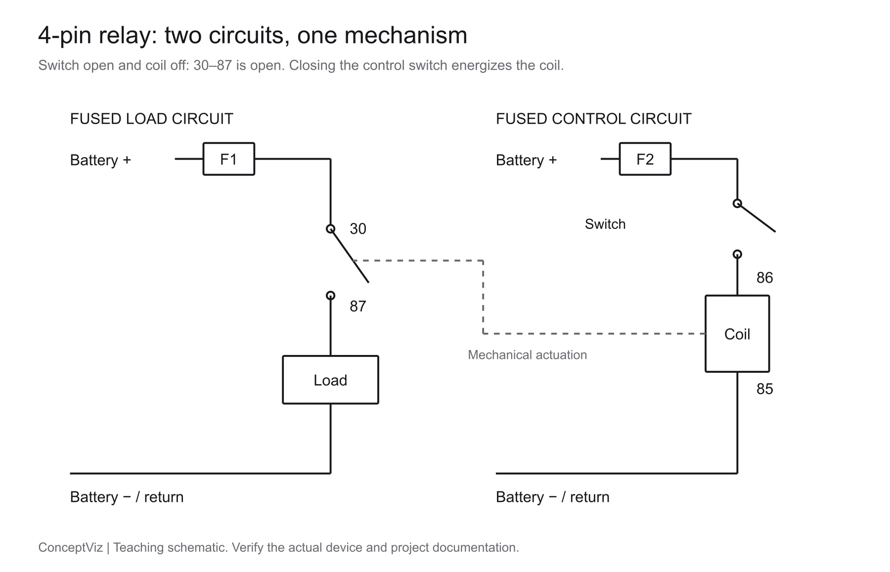
Coil off: the control switch and 30–87 contact are open. Closing the control switch would energize the coil and close the load contact. F1/F2 locations are schematic; physical fuse placement and ratings require the circuit design. Open the SVG.
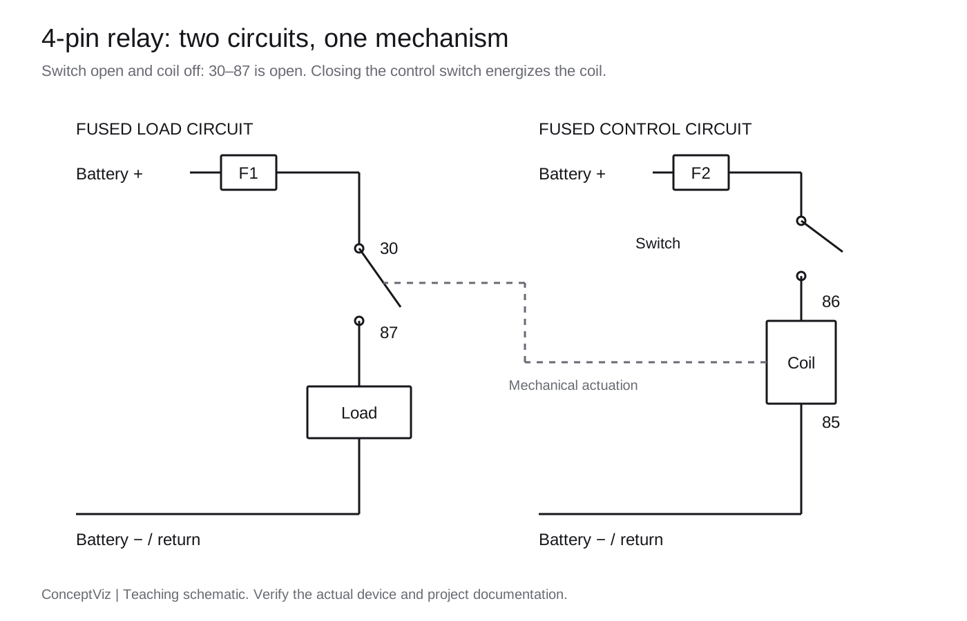
Read it in this order:
- Load supply: battery positive feeds the protected load branch, then terminal 30.
- Switched output: terminal 87 leads to the load. With the relay at rest, the gap between 30 and 87 interrupts this path.
- Load return: the other side of the load returns to the supply negative system. A complete loop is necessary; one labeled positive wire is not a complete circuit.
- Coil control: the separate protected control branch reaches terminal 86 through the switch.
- Coil return: terminal 85 completes the coil circuit to negative in this example.
The diagram uses positive-side switching for clarity. Some vehicle circuits switch the coil's return side instead, and electronic modules may drive or monitor the coil. Do not rewire a module-controlled circuit to match a generic drawing. Follow the vehicle's circuit documentation, including any suppression and diagnostic requirements.
For a classroom exercise, describe the state change before adding more components: switch open, coil off, load contact open; then switch closed, coil energized, load contact closed. This is a conceptual check, not an instruction to energize an unidentified relay. In an installed vehicle, use the manufacturer's isolation procedure before inspecting or changing wiring.
A 5-pin changeover relay adds 87a
A conventional five-pin changeover relay has a common contact that selects between two outputs. At rest, 30 connects to 87a. When the coil is energized, 30 disconnects from 87a and connects to 87. The extra pin is useful when the required output depends on whether the control is active or inactive.
| Coil state | 30 to 87 | 30 to 87a |
|---|---|---|
| De-energized | Open | Closed |
| Energized | Closed | Open |
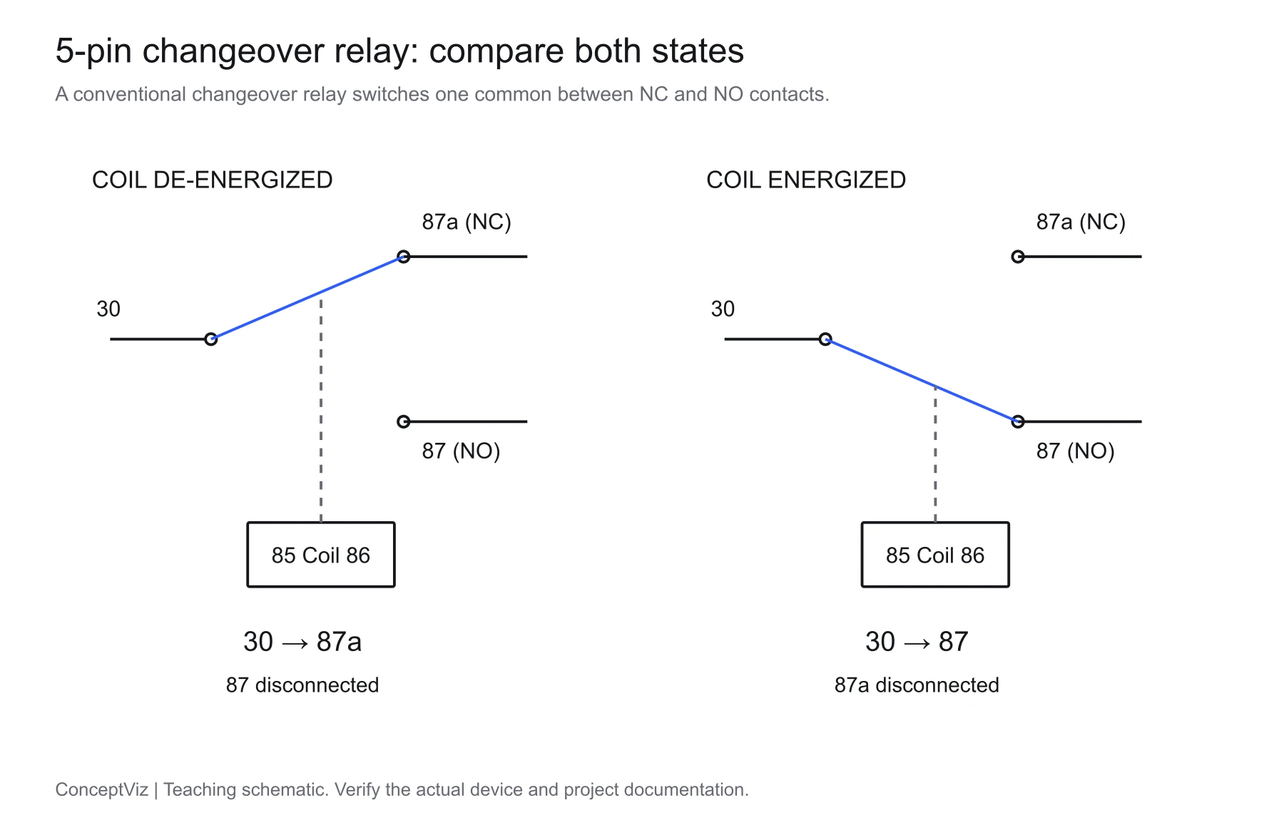
Blue identifies the selected contact path. These are two states of one changeover mechanism, not two separate switches to wire together. Open the SVG.
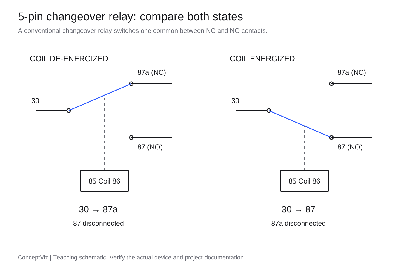
If a changeover relay is used only for normally open switching, the unused 87a connection still needs to be managed according to the harness design. It can become live when the coil is off because it connects to the common. A loose or exposed unused terminal is not made harmless by calling it “unused.”
Do not assume that five pins always mean changeover. Some relays have two terminals marked 87, providing two normally open outputs. That is a different contact arrangement from one 87 and one 87a. The manufacturer's case diagram and part number settle the question; pin count and case shape do not. The common-to-NO and common-to-NC paths may also have different current ratings, so check both rather than borrowing the larger number for either path.
Coil polarity and suppression diodes
An unsuppressed, ordinary coil may operate with either polarity, but that observation is not a safe universal rule for packaged automotive relays. An internal diode changes the requirement. In the convention illustrated here, 86 is positive and 85 is negative; the diode is connected across the coil with its cathode toward the positive end.
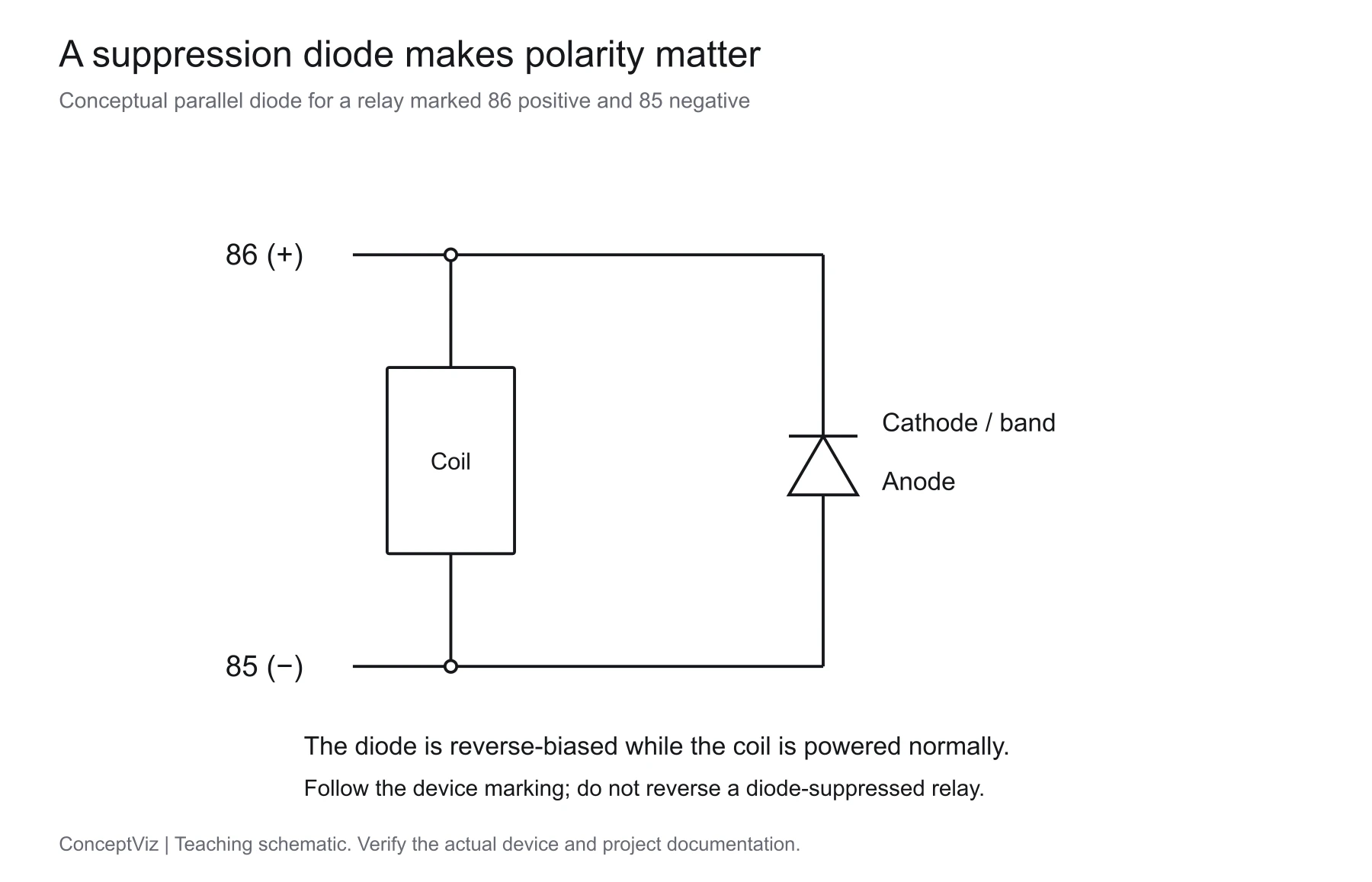
The diode is reverse-biased during normal coil energization. Its cathode bar corresponds to the band on a conventional physical diode. This explains a marked relay; it is not a specification for adding a diode to any vehicle circuit. Open the SVG.
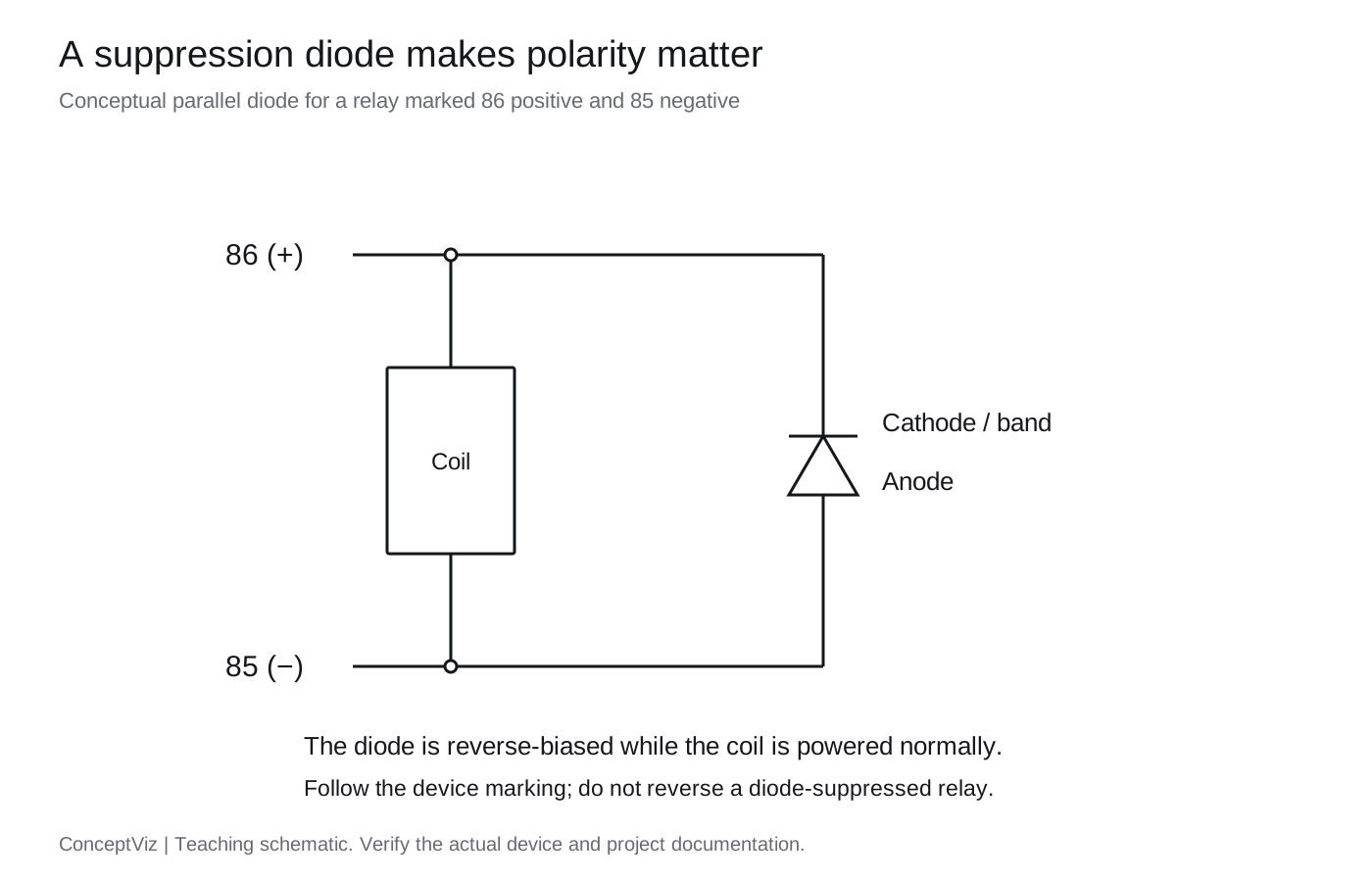
When the coil is switched off, the magnetic field collapses and can produce a voltage transient. Suppression components address that transient. Reversing a diode-suppressed relay can forward-bias the diode across the supply, causing excessive current or damage. Read the case symbol and datasheet before assigning polarity, even if another relay with the same-looking socket worked in the opposite orientation.
A resistor symbol across the coil indicates a different suppression arrangement from a diode. Neither should be confused with the main load or a resistor in series with the coil. Suppression can affect release behavior and driver compatibility, so replacing a relay requires more than matching the number of pins. HELLA documents both parallel resistor and diode versions in its coil-circuit explanation.
Turn a relay diagram into a useful drawing brief
Before generating a visual, collect a short connection list from the verified source drawing. Separate facts you know from values that still need checking. A clear brief identifies the relay type, coil voltage, terminal numbers, normal state, load and return paths, and suppression if present.
For example, a teaching-only prompt can read:
Draw a conventional 4-pin normally open automotive relay schematic.
Use 85 for coil negative, 86 for coil positive, 30 for common,
and 87 for the normally open output. Show separate protected load
and control branches, a positive-side control switch, and both returns.
Show the coil de-energized. Mark the mechanical link with a dashed line.
Label protective devices F1 and F2 without inventing ratings.
Add a note that this is a functional schematic, not a socket footprint.
Use the Wiring Diagram Maker for a labeled draft. If the goal is to explain operation rather than route wires to terminals, the Schematic Diagram Maker is another suitable starting point. For a whole facility's utility, transformers and feeders, use a single-line diagram instead. These views answer different questions, so avoid forcing all of them onto one sheet.
AI can transpose terminal labels, merge the coil with the contacts or draw a junction where two wires only cross. Inspect the actual result, not just the prompt. The precise figures in this article were drawn as explicit paths and labels and reviewed against the stated contact behavior. They are references for comparison, not evidence that every generated draft will be correct.
Check the diagram before anyone uses it
Use this review as a reading and documentation exercise with the circuit isolated according to its manufacturer's procedure. It does not require powering the vehicle or bridging terminals.
| Check | What a satisfactory drawing shows |
|---|---|
| Exact device | Part number or source document, rather than only “5-pin relay” |
| Coil circuit | Both 85 and 86 connected as specified; voltage and polarity identified |
| Contact state | One clearly named coil state with the corresponding 30/87/87a path |
| Supply and return | Complete loops, without an accidental connection between coil and contacts |
| Protection | Identified protective devices; values come from the design, not a relay label |
| Physical mapping | Terminal numbers checked against the actual socket view and orientation |
| Revision | Changes and unresolved assumptions noted before the diagram is shared |
Two common drawing problems are worth checking separately. First, a crossing is ambiguous if the drawing alternates between dots, line jumps and unmarked intersections. Choose one junction convention and use it consistently. Second, the underside view of a relay and the wire-entry view of its socket can appear mirrored. A neat visual can still be wrong when copied from the opposite side. Label the view instead of relying on visual resemblance.
For a suspected hardware fault, the next step is the manufacturer's diagnostic procedure, not an improvised live jumper. A click alone does not demonstrate that contacts can carry the required load; a diagram alone does not establish component condition. If the work goes beyond identifying the circuit on paper, have a suitably qualified automotive technician check it.
If you need software for a larger harness or documented drawing set, compare the workflows in our electrical wiring diagram software guide. Keep the verified schematic and the actual parts information alongside the edited drawing so a later revision remains traceable.
Frequently asked questions
What are pins 85 and 86 on a relay?
They are the coil terminals. This guide follows the conventional automotive assignment of 85 negative and 86 positive. Confirm the actual relay marking, especially when a suppression diode is present.
What is the difference between 87 and 87a?
87 is the normally open contact; it connects to common 30 when the coil is energized. 87a is the normally closed contact; it connects to 30 while the coil is de-energized on a conventional changeover relay.
Does every five-pin relay have an 87a terminal?
No. Some five-pin relays have two normally open outputs marked 87. Read the printed contact diagram and part-specific datasheet instead of identifying the relay by pin count.
Can I swap pins 85 and 86?
Do not assume you can. A plain unsuppressed coil may tolerate either polarity, but a diode-suppressed relay requires the marked polarity. Electronic relay assemblies and vehicle drivers can impose additional requirements.
Is a 30 A relay supposed to use a 30 A fuse?
Not automatically. A contact-current rating is not a universal fuse specification. Protection must be selected for the actual conductors, load, inrush and circuit requirements.
Is the pin layout in this guide a socket diagram?
No. The drawings show functions and contact states. Physical pin arrangements and viewing directions vary. Check the relay and socket documentation before mapping the numbered functions to blades.
Can I use an AI-generated relay wiring diagram directly?
Review it first against the real device and circuit documentation. Check every pin number, contact state, junction, polarity and return path. A generated illustration does not select safe wire sizes or protection ratings.
Wiring Diagram Maker
Turn a verified connection list into a visual draft. Keep the terminal numbers, normal state and source documentation with the diagram.
Create a connection diagram →More Posts

How to Create Scatter Plots in Excel: Step-by-Step Guide (2026)
Learn how to make scatter plots in Excel with trend lines, labels, and formatting. Complete guide with screenshots and tips for research data visualization.

8 Best Free ChemDraw Alternatives in 2026 (For Drawing Chemical Structures)
Compare the best free ChemDraw alternatives: ChemSketch, MarvinSketch, MolView, ChemDoodle & more. Draw chemical structures without expensive subscriptions.
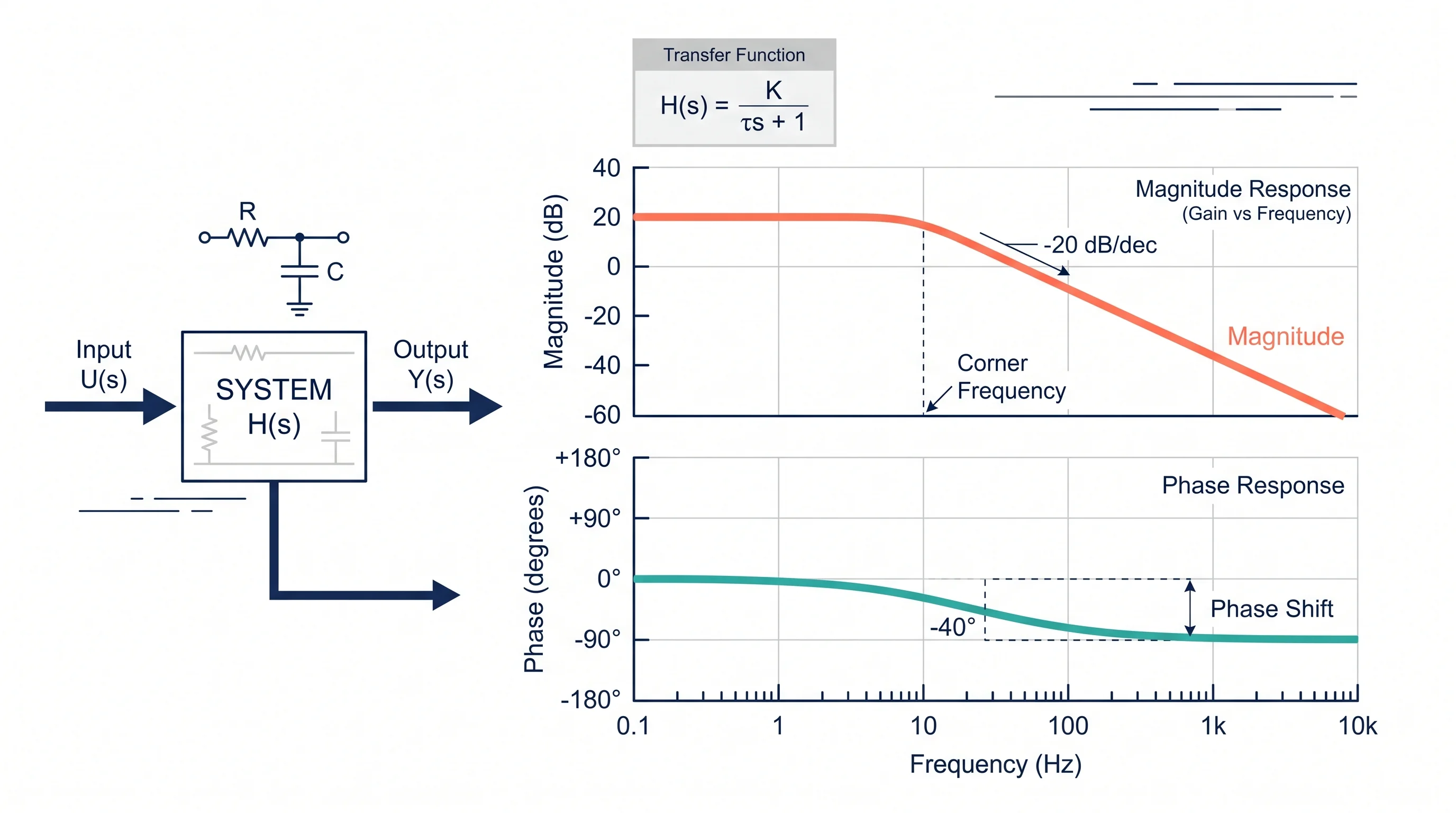
Bode Plot Generator Guide: Make Magnitude and Phase Plots from a Transfer Function
Learn how to use a Bode plot generator, enter transfer functions correctly, read magnitude and phase plots, and avoid common frequency-response mistakes.