Control Panel Wiring Diagram Generator for Motor Control and PLC Panels
Generate a control panel wiring diagram from a text prompt: motor starter, PLC inputs and outputs, panel layout. With an exact DOL start/stop ladder diagram.
Create Your Control Panel Wiring Diagram
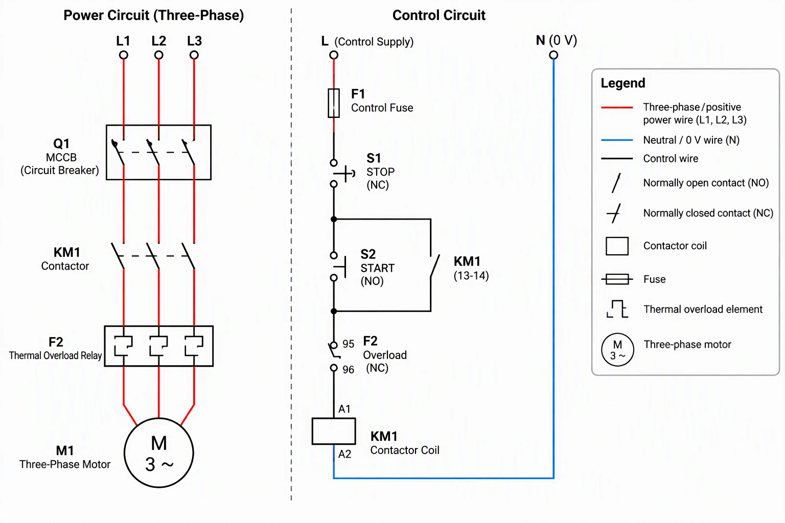 Example: DOL motor starter, power and controlView full size
Preview is free on this page ·
Your control panel wiring diagram will appear here
AI diagrams are drafts. Check every contact, common, and polarity before use.
Control Panel Wiring Diagram Examples
Two exact diagrams drawn in code, plus two AI diagrams with their known flaws noted. AI diagrams need human review.
DOL start/stop control ladder diagram (exact diagram)
Drawn in code, not by AI. STOP is normally closed and in series, START is normally open with the KM1 13-14 seal-in contact in parallel, the overload contact F2 95-96 is normally closed in the coil rung, the control fuse F1 feeds the left rail so all three rungs are protected, and the coil returns to the other rail. Two lamp rungs show RUN from KM1 23-24 and OVERLOAD from F2 97-98. The power circuit is not shown, and terminal markings follow common IEC practice, so check them against your parts.
The same start/stop logic as PLC ladder logic (exact diagram)
Drawn in code. The same seal-in logic written as PLC ladder logic. Field normally closed contacts for STOP and overload read as true while healthy, so they appear as open-symbol contacts in the program. Addressing and instruction names differ by PLC maker, so treat it as a planning sketch.
DOL motor starter, power and control (AI diagram)
AI-generated from the prompt shown. We checked the protective order and the control logic: the breaker is upstream of the contactor, the overload relay sits between the contactor and the motor, STOP is normally closed in series, START is normally open with the KM1 13-14 contact in parallel, and the overload contact F2 95-96 is normally closed in the coil rung. Known flaws: the control supply "L" and "N" are not tied to the power circuit; the legend colors and symbols do not fully match the drawing (all three phase wires are red but the legend calls red "positive"); the STOP pushbutton symbol is not a standard symbol and its normally closed state is hard to read; the legend symbols are informal; and the main contacts have no terminal numbers.
Control panel back plate layout (AI illustration)
AI-generated from the prompt shown. The layout idea is right: power devices on one DIN rail, control devices on another, wire ducts between and around them, and a terminal block row along the bottom. Known flaws: it is a rendering, not a schematic; wires end in the ducts without real connections; part counts and wire colors are invented; device labels are K1 and F1 here while the schematic calls them KM1 and F2 (tags are illustrative only); and the voltage labels are examples, not a recommendation.
For wiring outside control panels, such as home, automotive, or appliance systems, use the Wiring Diagram Maker. For 12V and DC battery systems, see the Battery Wiring Diagram Generator and the Boat Wiring Diagram Generator. If your control circuit uses relays, read the relay wiring diagram guide.
Standards pages (checked October 2026): NFPA 79, IEC 60204-1, and UL 508A.
What a control panel wiring diagram shows
A control panel wiring diagram documents how the devices inside an industrial control cabinet are connected. In practice it is a small set of drawings: a power circuit (supply, breaker, contactor, overload relay, motor), a control circuit (pushbuttons, relay contacts, coils, lamps), PLC input and output wiring, and a layout of where each device sits on the back plate. Electricians use them to build and fault-find, integrators use them to hand a machine over, and maintenance teams use them to work out why something will not start. Describe the part you need in the prompt box, generate a draft, and compare it with the exact diagrams in the gallery above.
DOL starter: the power circuit and the control circuit
- A direct-on-line (DOL) starter connects a three-phase motor straight to the supply through a contactor. It is the simplest motor starter and the usual starting point for pumps, fans, and winch or windlass motors.
- Power circuit: supply, then a breaker or motor protection device, then the contactor main contacts, then the thermal overload relay, then the motor. Protection sits upstream of the load, and the overload sits between the contactor and the motor.
- Control circuit: a normally closed STOP pushbutton in series, a normally open START pushbutton, the contactor auxiliary contact (commonly numbered 13-14) in parallel with START as the seal-in, the overload relay normally closed contact (commonly 95-96) in series, and the contactor coil (A1-A2).
- STOP and the overload contact are wired normally closed on purpose: a broken wire or a tripped overload opens the coil rung and stops the motor, so the safe state is the default state.
- This is the pattern the exact ladder diagram on this page draws, rung by rung.
How to read the ladder diagram
- A ladder diagram draws the control circuit between two vertical rails, with each rung a separate path from one rail to the other. Read it left to right: current must find a closed path through every contact on the rung to energize the coil at the end.
- In the exact diagram, pressing START closes the path through STOP, START and the overload contact to coil KM1. The coil pulls in and closes its own 13-14 contact in parallel with START, so releasing START does not drop the coil. That is the seal-in, also called a holding or latching circuit.
- Pressing STOP opens the rung, the coil drops out, and the seal-in opens with it. The motor does not restart until START is pressed again, which is why a seal-in circuit also prevents automatic restart after a power loss.
PLC input and output wiring on 24V DC
- PLC wiring splits into three groups: the PLC power supply terminals, the input group with its common terminal, and the output group with its common terminal. Inputs are usually grouped on a shared common (for example 1M) and outputs on another, so the common terminals decide how every device in the group must be wired.
- A common rule for digital inputs: a PNP (sourcing) sensor switches +24V to the input, and the input common is tied to 0V. An NPN sensor is the opposite. Check the input module datasheet for the exact arrangement, because it differs by maker and by module.
- Sourcing outputs switch +24V to the load: the output common (often marked 1L+ or similar) goes to +24V and each load returns to 0V. Interposing relays are common between PLC outputs and larger coils.
- Keep polarity consistent: the supply, the PLC power terminals, the commons and the loads must all agree on which rail is +24V and which is 0V. We tested AI generation on this wiring: our PLC input and output test diagram got the input common wiring wrong, so this page uses an exact ladder logic diagram instead of an AI wiring drawing. Check any PLC wiring, generated or not, against the PLC maker’s wiring manual.
- The second exact diagram shows the same start/stop logic as PLC ladder logic. A field normally closed contact keeps its input on while healthy, so it is read as an open-symbol contact in the program.
PNP and NPN sensors on PLC inputs: sinking and sourcing
- A PNP sensor switches +24V to its signal wire when it detects something. It works with an input whose common is tied to 0V. Current flows from the sensor into the input and out through the common to 0V. This is the usual arrangement in Europe and in many newer designs, and it is the one the PLC logic on this page assumes.
- An NPN sensor switches 0V to its signal wire instead. It works with an input whose common is tied to +24V.
- Both types also need power: commonly brown to +24V, blue to 0V, and black as the signal output (check the sensor datasheet, because colors and pinouts vary).
- A plain contact, such as a pushbutton or a relay contact, works with either arrangement. Connect one side to the input and the other side to the rail opposite the common: +24V when the common is on 0V, and 0V when the common is on +24V.
- Do not mix PNP and NPN devices on one input group, because the group has a single common. Some modules fix the arrangement and some let you choose it by how you wire the common. Terms such as sinking and sourcing are used differently by different makers, so confirm against the input module datasheet before you wire.
Panel layout: what goes where
- A layout drawing places devices on the back plate. Common practice groups power devices (breakers, contactors, overload relays) together and control devices (power supply, PLC, relays) together, with wire ducts between them and a terminal block row where field wiring enters. Separating the zones keeps mains-voltage wiring away from low-voltage signals and makes the panel easier to service.
- Mount devices on DIN rails, leave room in the ducts for the wires you will add later, and label every device and terminal with the same tag as on the schematic. A layout is only useful if the tags match the wiring diagram.
- Spacing, heat, enclosure rating, grounding and wire sizing are design decisions. Take them from the device datasheets and the standards that apply to your panel, not from a picture.
How to generate a control panel wiring diagram from text
- Say which drawing you want: power circuit, control circuit, PLC I/O, or panel layout. One drawing per prompt gives better results than all four at once.
- List the devices with their tags (Q1, KM1, F2, M1, S1, S2) and the order of the power path.
- For control circuits, state each contact and whether it is normally open or normally closed, and say which contact is in parallel with which.
- For PLC wiring, name the input and output terminals and the commons, and say where each common connects.
- Ask for generic components, no brand names, short English labels and a legend. Generate, then trace every wire against your own parts. Re-prompt to fix anything that is wrong.
Exact diagrams vs AI illustration on this page
The two exact diagrams are drawn in code, so every contact, rung and label is placed on purpose. The two AI diagrams were generated from the prompts shown. We checked each one for protective order, normally open and normally closed contacts, seal-in wiring, overload contact placement and label spelling, and each caption lists the flaws we found. Two AI attempts at PLC input and output wiring were left out because the input common and sensor wires were connected wrongly. AI output is useful for a quick draft, but it can leave out a connection, tie a common to the wrong place or draw an informal symbol. A diagram from this page is a planning sketch. It is not a construction drawing, a wire list or a bill of materials, and it does not replace the device manufacturers’ documentation, the standards that apply to your machine or panel, or a licensed electrician.
Standards that apply to industrial control panels
Industrial control panels and the electrical equipment of machines are covered by standards such as NFPA 79 (Electrical Standard for Industrial Machinery), IEC 60204-1 (Safety of machinery, electrical equipment of machines, general requirements) and UL 508A (Standard for Industrial Control Panels). Which one applies depends on the machine, the market and who inspects it, and each is revised periodically, so buy the current edition from the publisher. Diagrams from this page do not claim compliance with any of them. Names checked October 2026 on the publishers’ pages: NFPA, IEC and UL.
Frequently Asked Questions
Related Engineering Tools
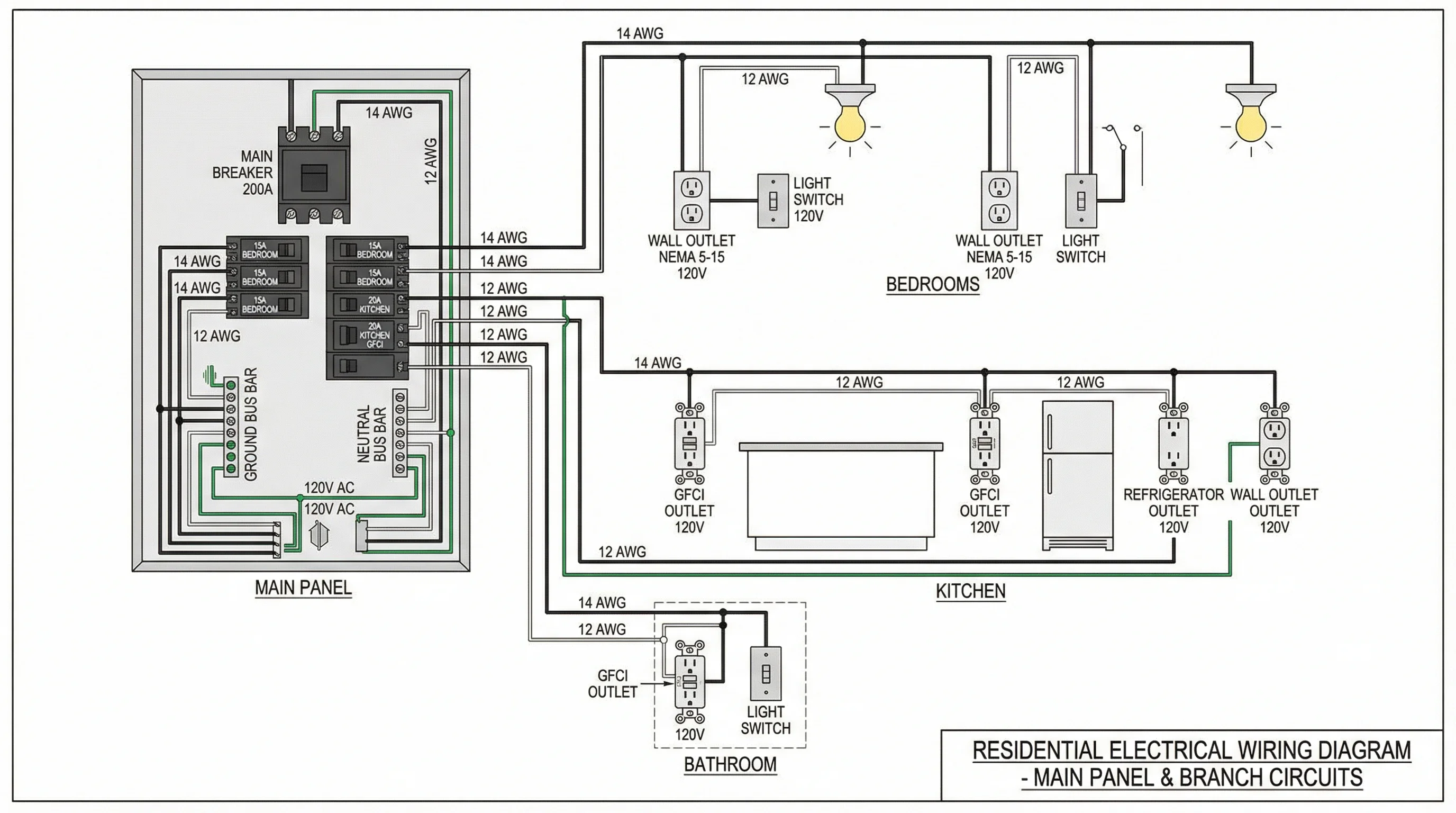 Physics
Wiring Diagram Maker
Wiring diagrams for home, automotive, appliance, and industrial systems from a plain-English description.
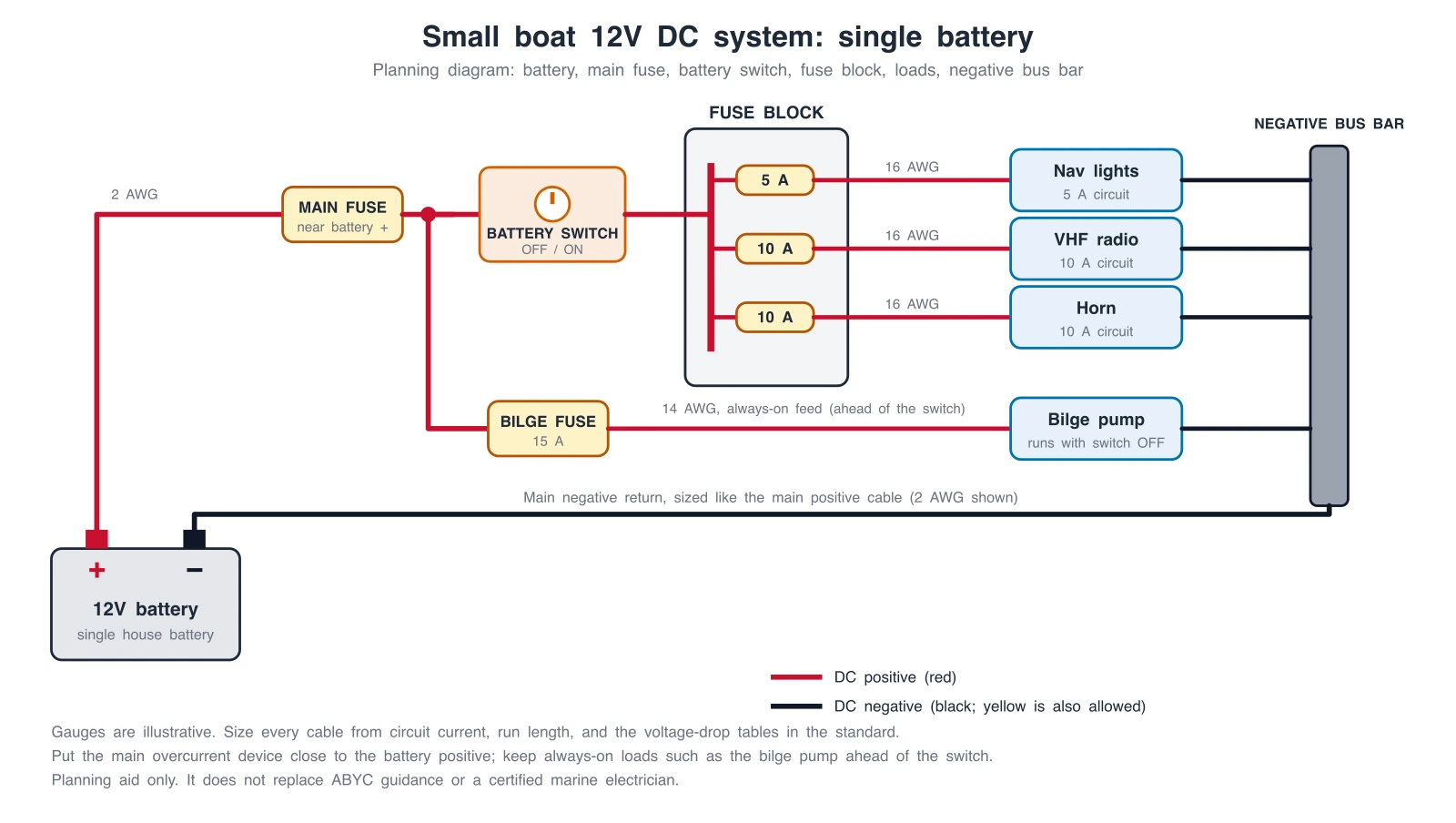 Engineering
Boat Wiring Diagram Generator
Generate boat wiring diagrams: single and dual battery, battery switch, fuse block, bilge pump, and outboard systems, with exact reference diagrams.
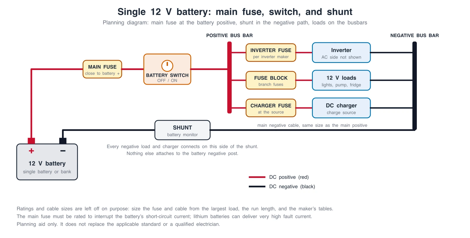 Engineering
Battery Wiring Diagram Generator
Generate battery wiring diagrams: main fuse, switch, shunt, series or parallel banks, and DC-DC charging, with exact reference diagrams.
 Engineering
Single-Line Diagram Generator
Facility-level one-line diagrams of sources, transformers, and feeders.