Three Phase Motor Wiring Diagram Generator for 3, 6, 9 and 12 Lead Motors
Exact 3 phase motor wiring diagrams for 3, 6, 9 and 12 lead motors: wye, delta, high and low voltage, T1 to T12. Follow your motor nameplate.
Three Phase Motor Wiring Diagrams by Lead Count
Exact diagrams drawn in code from a reviewed list of connections. Each shows the supply lines, the motor terminal studs, the jumpers and the winding layout. NEMA-style lead numbers, motor terminals only.
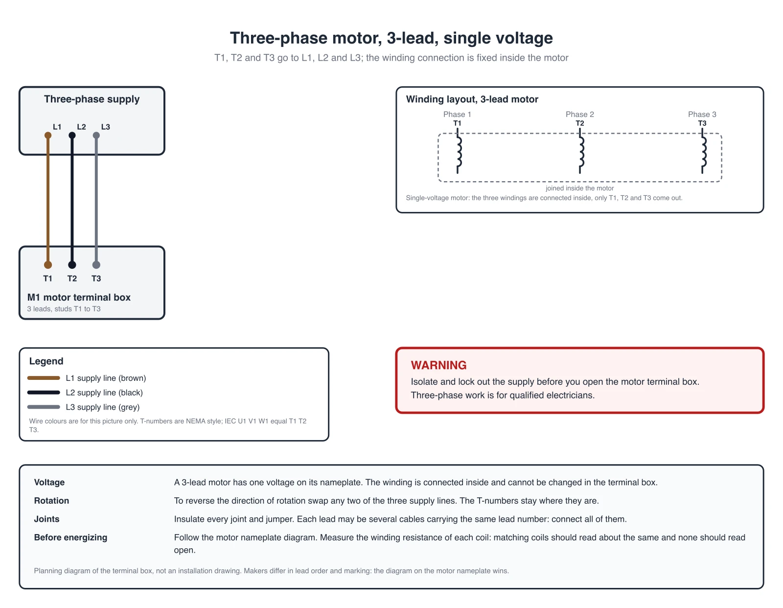
3-lead motor
A single-voltage motor with three leads. T1, T2 and T3 go to L1, L2 and L3. The winding is connected inside the motor, so there is nothing to change in the terminal box.
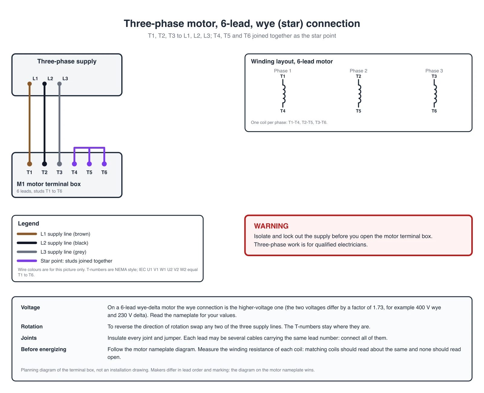
6-lead motor, wye (star)
T1, T2 and T3 to the supply, and T4, T5 and T6 joined together. On a 6-lead wye-delta motor this is the connection for the higher of its two supply voltages (the wye voltage on the nameplate).
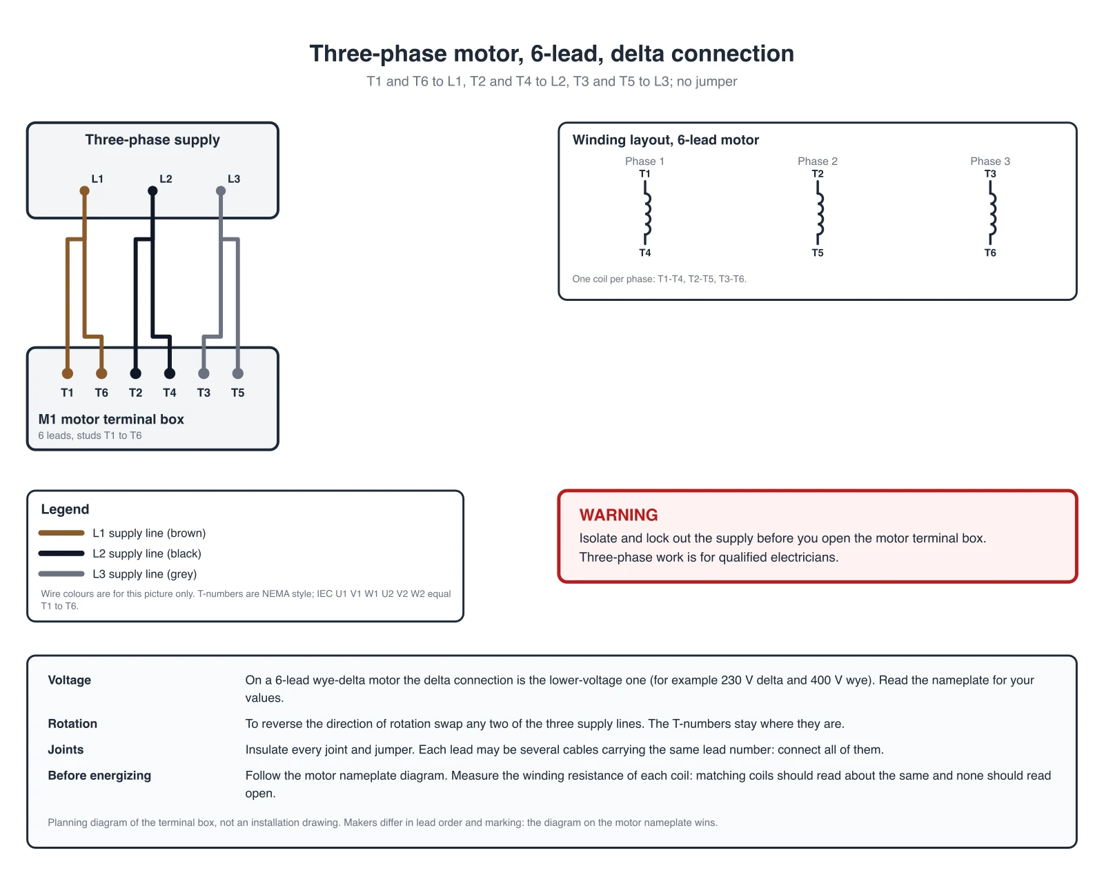
6-lead motor, delta
T1 with T6 to L1, T2 with T4 to L2, T3 with T5 to L3. No jumper: each supply line takes the end of one winding and the start of the next. On a 6-lead wye-delta motor this is the connection for the lower of its two supply voltages (the delta voltage on the nameplate).
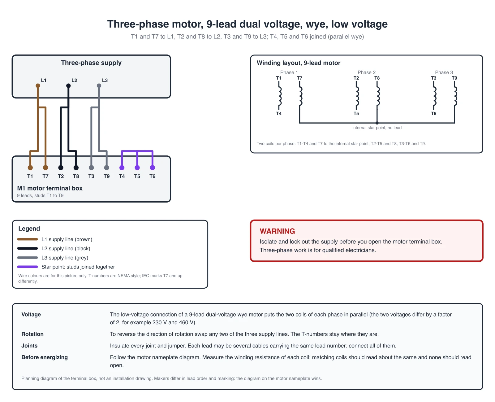
9-lead dual voltage, wye, low voltage
Parallel wye. T1 and T7 to L1, T2 and T8 to L2, T3 and T9 to L3, with T4, T5 and T6 joined together. The two coils of each phase share the load.
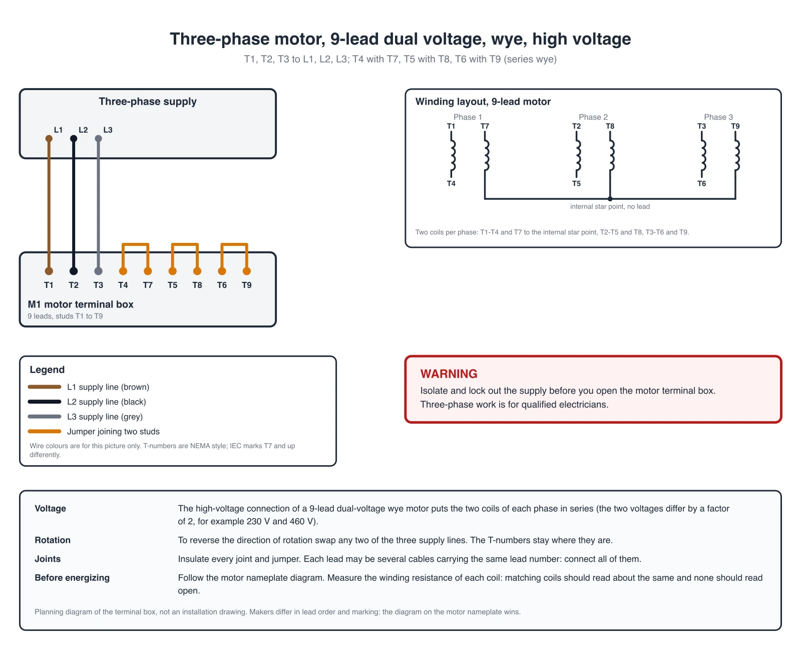
9-lead dual voltage, wye, high voltage
Series wye. T1, T2 and T3 to the supply, and three separate jumpers: T4 to T7, T5 to T8, T6 to T9. The two coils of each phase are in series.
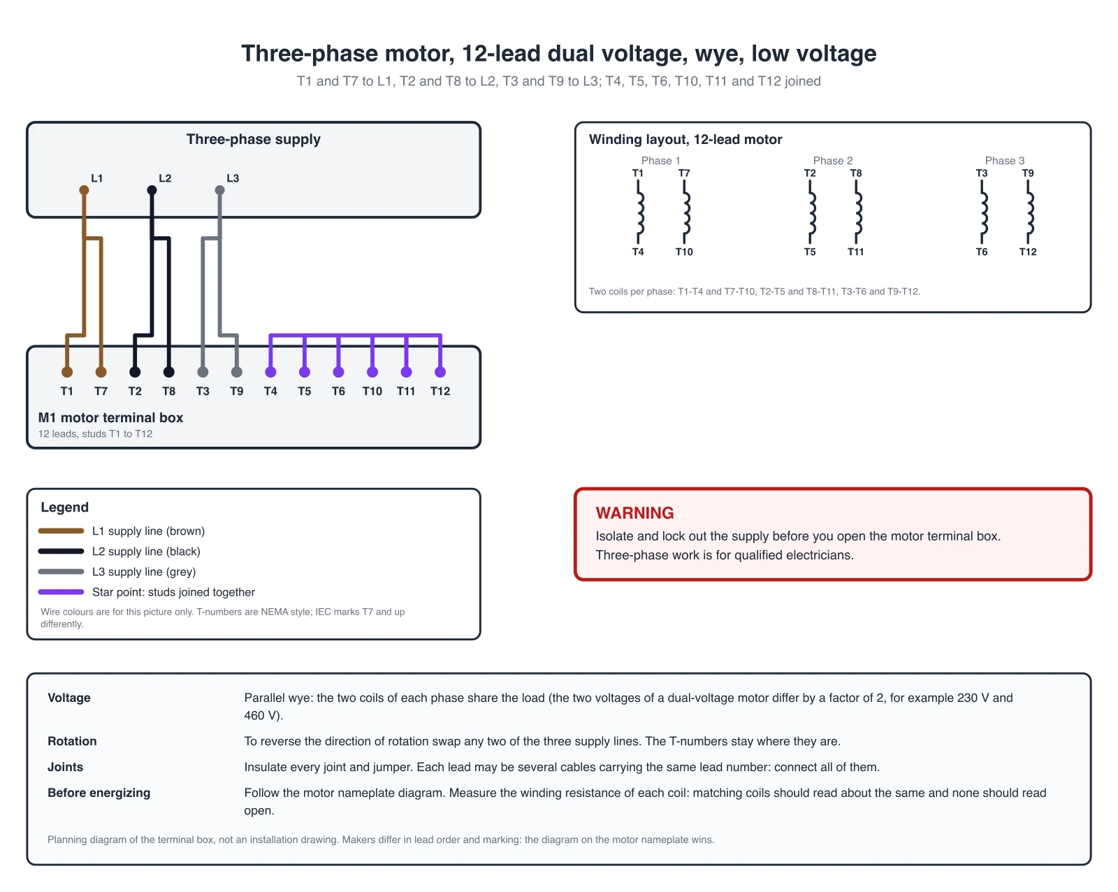
12-lead dual voltage, wye, low voltage
Parallel wye. T1 and T7 to L1, T2 and T8 to L2, T3 and T9 to L3, and all six of T4, T5, T6, T10, T11 and T12 joined into one star point.
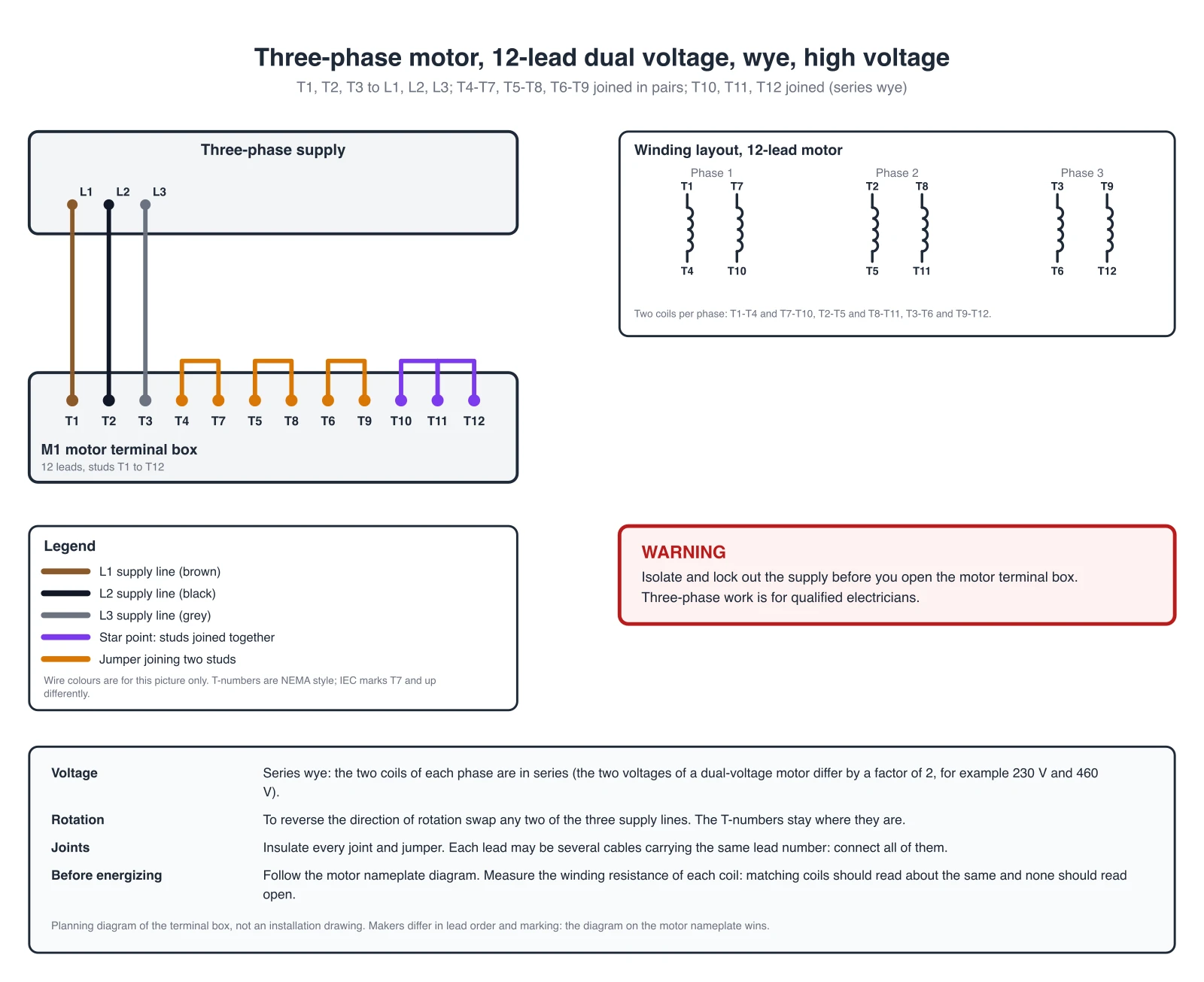
12-lead dual voltage, wye, high voltage
Series wye. T1, T2 and T3 to the supply, T4 to T7, T5 to T8 and T6 to T9 jumpered in pairs, and T10, T11 and T12 joined together as the star point.
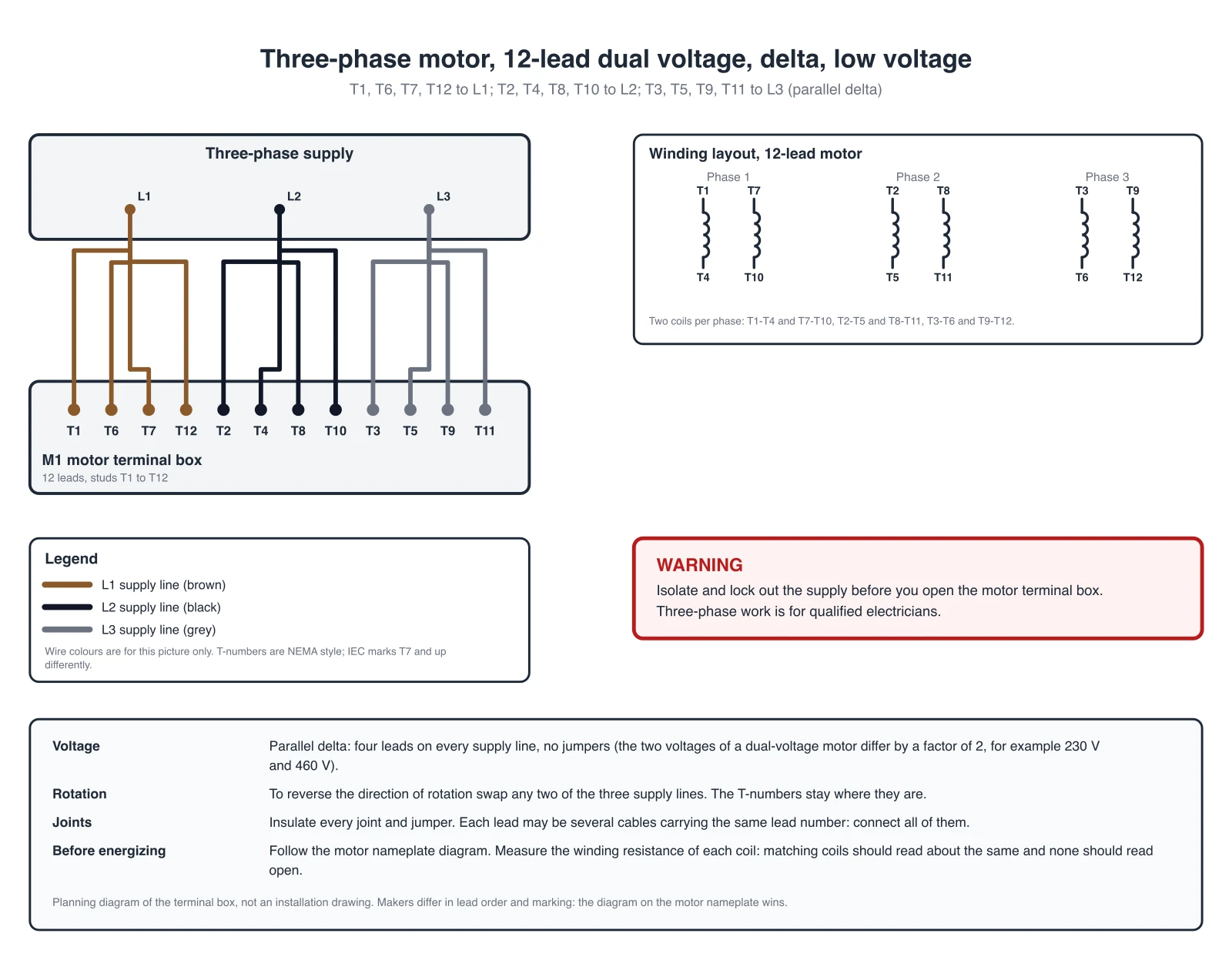
12-lead dual voltage, delta, low voltage
Parallel delta. Four leads on every supply line, no jumpers: T1, T6, T7 and T12 to L1, T2, T4, T8 and T10 to L2, T3, T5, T9 and T11 to L3.
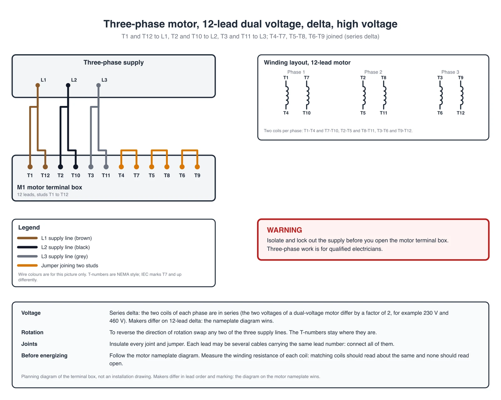
12-lead dual voltage, delta, high voltage
Series delta. T1 and T12 to L1, T2 and T10 to L2, T3 and T11 to L3, with T4 to T7, T5 to T8 and T6 to T9 jumpered in pairs. Makers differ on 12-lead delta, so the nameplate diagram wins.
Terminal Connection Table, T1 to T12
The same connections as the diagrams. Studs in one cell are joined to that supply line. A jumper joins the studs it lists, and the studs of one jumper are not joined to the line.
| Motor and connection | L1 | L2 | L3 | Jumpers |
|---|---|---|---|---|
| 3-lead motor | T1 | T2 | T3 | none |
| 6-lead motor, wye (star) | T1 | T2 | T3 | T4-T5-T6 |
| 6-lead motor, delta | T1 + T6 | T2 + T4 | T3 + T5 | none |
| 9-lead dual-voltage wye, low voltage (parallel) | T1 + T7 | T2 + T8 | T3 + T9 | T4-T5-T6 |
| 9-lead dual-voltage wye, high voltage (series) | T1 | T2 | T3 | T4-T7, T5-T8, T6-T9 |
| 12-lead dual-voltage wye, low voltage (parallel wye) | T1 + T7 | T2 + T8 | T3 + T9 | T4-T5-T6-T10-T11-T12 |
| 12-lead dual-voltage wye, high voltage (series wye) | T1 | T2 | T3 | T4-T7, T5-T8, T6-T9, T10-T11-T12 |
| 12-lead dual-voltage delta, low voltage (parallel delta) | T1 + T6 + T7 + T12 | T2 + T4 + T8 + T10 | T3 + T5 + T9 + T11 | none |
| 12-lead dual-voltage delta, high voltage (series delta) | T1 + T12 | T2 + T10 | T3 + T11 | T4-T7, T5-T8, T6-T9 |
IEC marking of the six main leads: U1 V1 W1 are T1 T2 T3 and U2 V2 W2 are T4 T5 T6. Lead arrangements of 12-lead motors differ between makers, so the nameplate diagram of your motor wins.
This page covers the motor terminals only. For the direct-on-line starter power circuit and the start/stop control ladder, see the Control Panel Wiring Diagram Generator. For other wiring, such as home, automotive, or appliance systems, use the Wiring Diagram Maker.
AI illustration of your motor wiring
Describe a motor and a connection to get a quick picture. AI images can draw wrong connections, so use the exact diagrams and the table above for the real connections and check every stud of an AI picture. You can also use the generator below to make an illustration of your own motor setup.
Generate an AI Motor Wiring Illustration
Example: Exact reference for this connection (drawn in code, not the AI output)View full sizePreview is free on this page ·
Your three phase motor wiring diagram will appear here
AI diagrams are drafts. Check every stud, jumper and supply line against your nameplate.
Connection sources (checked October 2026): Nidec Motor Corporation (US Motors) connection diagrams, including the 6-lead plate 438252 and the 12-lead plate 488075, Electric Motor Warehouse, motor connection diagrams, and Phoenix Phase Converters, three phase motor wiring diagrams. Terminal numbering follows the NEMA MG 1 style, which this page does not quote.
What a three phase motor wiring diagram shows
A three phase motor wiring diagram shows how the leads that come out of the motor windings are joined to each other and to the three supply lines L1, L2 and L3. The leads are numbered, T1 to T3 for the three-lead motor and up to T12 for the largest dual-voltage motors, and the diagram says which numbers go to which line and which numbers are joined by a jumper. It is the drawing electricians use to reconnect a motor for a different voltage, to replace a motor, or to check a motor that came without a diagram. This page draws the standard NEMA-style connections as exact diagrams and puts the same connections in a table. It covers the motor terminals only, not the starter or the control circuit.
How to read T1 to T12
- Each winding coil has two ends. The first end of the three phases is T1, T2 and T3, and the second ends are T4, T5 and T6, so the coils are T1-T4, T2-T5 and T3-T6 (the IEC marking for the same six leads is U1 V1 W1 and U2 V2 W2). A nine-lead or twelve-lead motor has a second set of coils per phase, with the ends T7 to T9 and T10 to T12.
- Dual-voltage motors are made by connecting those coils in parallel for the lower voltage and in series for the higher voltage. That is why the same motor has two diagrams, and why the table below has a low-voltage and a high-voltage row for the 9-lead and 12-lead motors.
- The ratio of the two voltages is 2 to 1 on a 9-lead or 12-lead dual-voltage motor (for example 230 V and 460 V) and 1.73 to 1 on a 6-lead wye-delta motor (for example 400 V wye and 230 V delta). Your nameplate gives the real values.
3-lead and 6-lead motors, wye and delta
- A three-lead motor is a single-voltage motor whose winding is connected inside. Connect T1, T2 and T3 to L1, L2 and L3.
- A six-lead motor has each coil brought out. In the wye (star) connection the three coil ends T4, T5 and T6 are joined and T1, T2 and T3 go to the supply. In the delta connection T1 and T6 go to L1, T2 and T4 to L2, and T3 and T5 to L3.
- Wye and delta are the two operating connections of a 6-lead motor, one for each of its two supply voltages. A star-delta starter starts the motor in wye and then switches it to delta, which only works when the delta voltage on the nameplate equals your supply voltage, for example a 400 V delta / 690 V wye motor on a 400 V supply. A 230 V delta / 400 V wye motor on a 400 V supply must run in wye and cannot be star-delta started. The starter makes the joints with contactors, so all six leads go to the starter. The starter power and control circuits are outside this page. For a direct-on-line starter, see the control panel page linked below.
9-lead dual-voltage wye motors
- A nine-lead motor is a dual-voltage wye motor. The ends that would be T10, T11 and T12 are joined at a star point inside the motor, which is why those three leads do not exist.
- For the low voltage the two coils of each phase are in parallel: T1 and T7 go to L1, T2 and T8 to L2, T3 and T9 to L3, and T4, T5 and T6 are joined together. For the high voltage they are in series: T1, T2 and T3 go to the supply, and T4 is joined to T7, T5 to T8 and T6 to T9 with three separate jumpers. Do not join the three pairs to each other.
12-lead motors: wye or delta, high or low voltage
- A twelve-lead motor has two full coils per phase and no internal joints, so it can be connected as a wye or a delta, at the low or the high voltage. That is four diagrams on this page. The wye ones join the star point, T4, T5, T6, T10, T11 and T12 at the low voltage, and T10, T11 and T12 at the high voltage. The delta ones need no star point, and the low-voltage delta puts four leads on every supply line.
- These are the connections published on NEMA-style connection plates (see the sources below). Makers differ. Some publish another lead arrangement for the 12-lead delta, and other 12-lead constructions exist, for example two separate wye windings. If your nameplate shows something different from this page, follow the nameplate, and do not mix the two.
Reversing rotation
To reverse the direction of rotation of a three-phase motor, swap any two of the three supply lines, for example L1 and L2. The jumpers and the T-numbers stay where they are. On a motor that is fed by a starter, swap the lines at the supply side of the starter or as the starter drawing says.
Before you energize the motor
- Isolate the supply and lock it out before you open the terminal box.
- Follow the connection diagram on the nameplate or inside the terminal box lid. If it differs from a drawing you found online, the nameplate wins.
- Measure the winding resistance of each coil. Matching coils should read about the same, and no coil should read open. Then test the insulation resistance from the windings to ground (a megger test) with the voltage and minimum value the motor maker gives. If the lead tags are missing or unreadable, have a motor shop identify the leads, do not guess.
- Insulate every joint and jumper, close the terminal box and check the rotation direction with the load uncoupled where that is possible. Then have a qualified electrician confirm the connection before the motor is powered.
Exact diagrams vs AI drafts
The nine diagrams above are exact reference diagrams. They are drawn in code from a reviewed list of connections, and a checker compares every drawing with a reference table of the standard connections, so each stud T1 to T12 is connected exactly once and as listed. We do not show AI-generated wiring images as examples, because image models often draw wrong connections, for example a stud used twice, a jumper to the wrong stud, or two supply lines joined. The generator on this page still produces an AI illustration from your prompt. Treat it as a rough picture, compare it with the exact diagrams and with your nameplate, and let a qualified electrician decide what gets installed. A diagram from this page is a planning picture of the terminal box. It is not an installation drawing and it does not replace the motor maker’s instructions or the electrical code that applies in your area.
Frequently Asked Questions
Related Engineering Tools
 Engineering
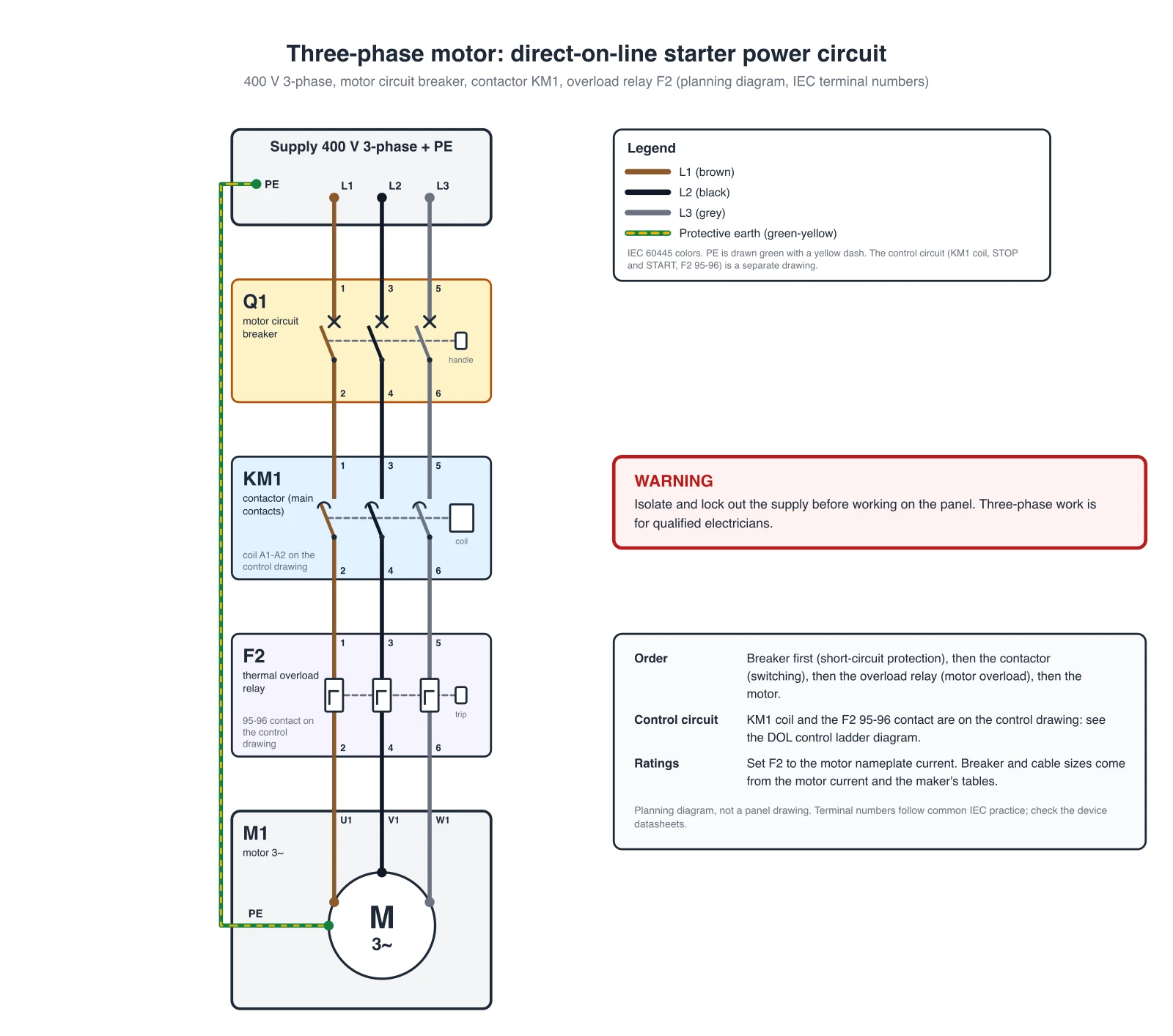
Control Panel Wiring Diagram Generator
Direct-on-line motor starter power circuit and start/stop ladder diagram, PLC I/O and panel layouts.
 Physics
Wiring Diagram Maker
Wiring diagrams for home, automotive, appliance, and industrial systems from a plain-English description.
 Engineering
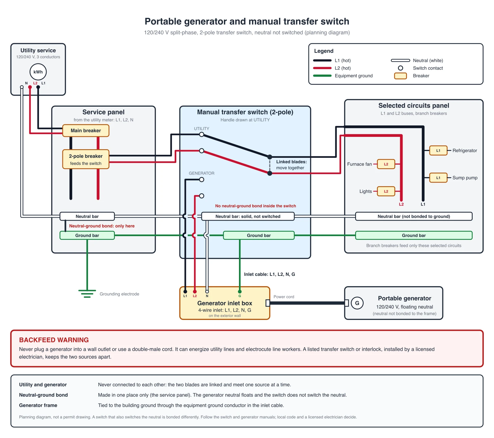
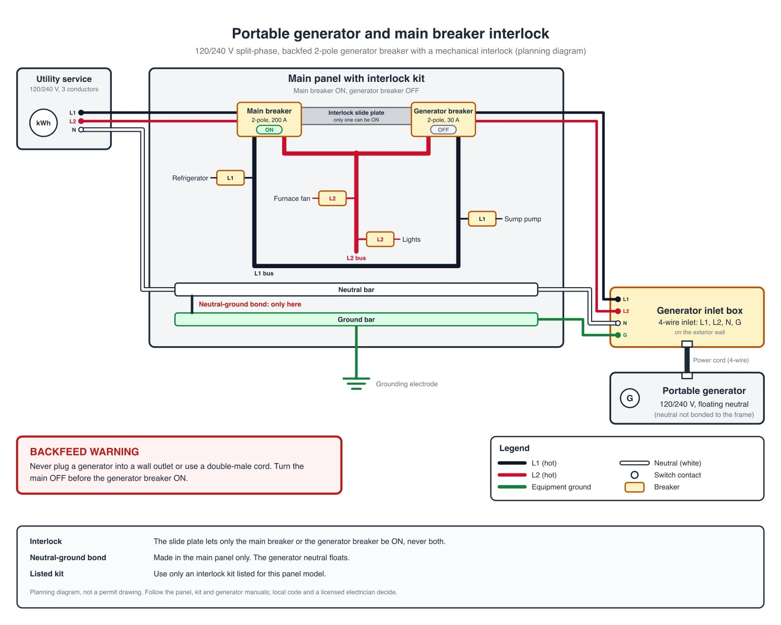
Generator Transfer Switch Wiring Diagram Builder
Manual switch, interlock kit and ATS hookups with exact reference diagrams.
 Engineering
Single-Line Diagram Generator
Facility-level one-line diagrams of sources, transformers, and feeders.