Three Way Switch Wiring Diagram Generator Exact Layouts
Exact 3-way switch wiring diagrams: power at the switch and power at the light, with common and travelers marked. Planning drawings, not code advice.
Three Way Switch Wiring Diagrams
Exact diagrams drawn in code from a reviewed list of connections. Each shows the supply, both switches with the common and the two travelers, the light, the neutral, the ground and the cable runs. One light, two switches, 120 V.
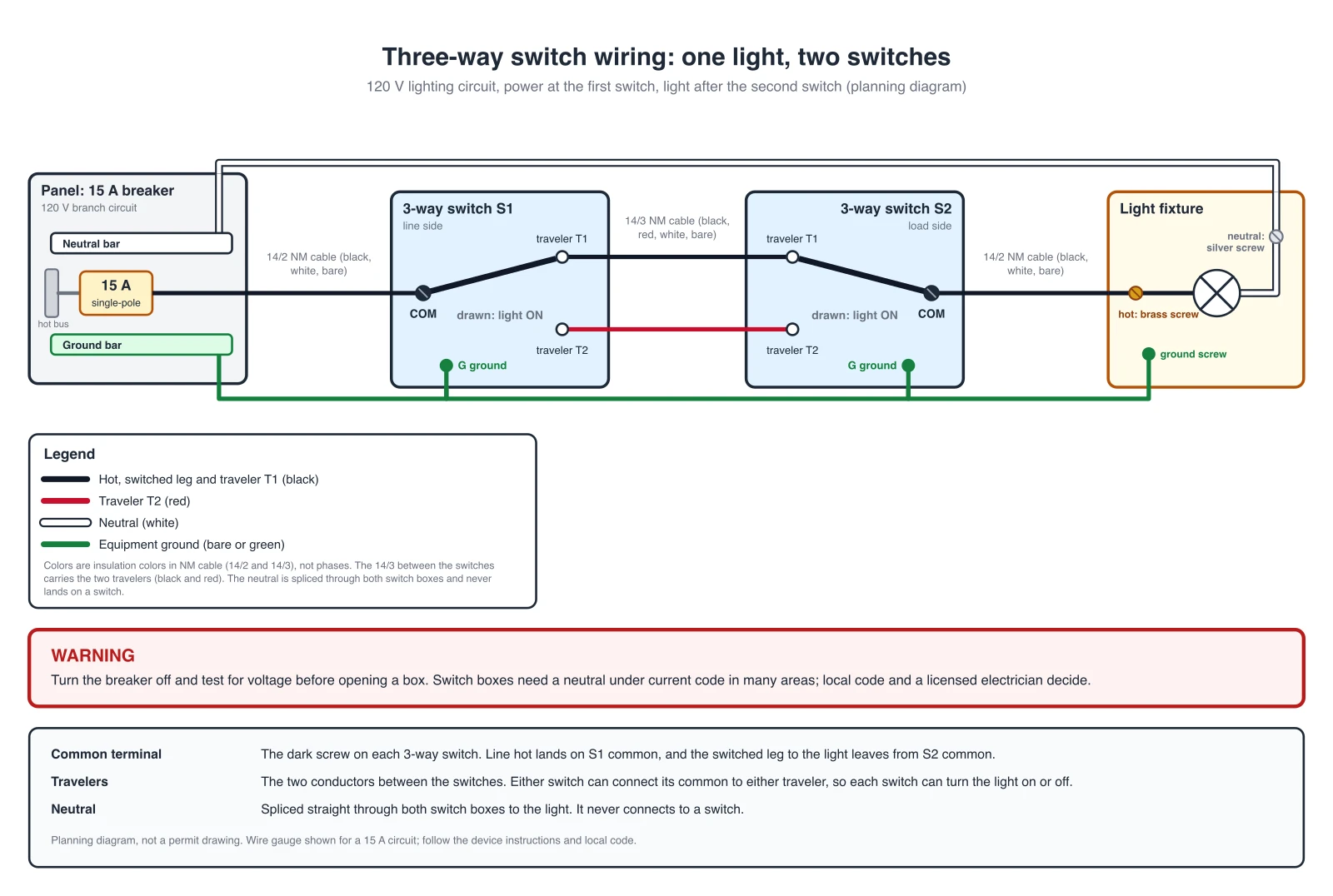
Power at the first switch, light at the end of the run
The most common layout. The supply cable enters the box of S1. The hot goes to the common of S1, the two travelers go to the other switch, and the common of S2 carries the switched hot to the light. The neutral goes through both switch boxes without touching a switch.
Cable runs: 14/2 from the panel to S1, 14/3 between S1 and S2, 14/2 from S2 to the light.
Known simplification: the neutral is drawn as one wire from the panel to the light. In the boxes it is spliced through both switch boxes with a pigtail, and the cable colors are those of NM cable.
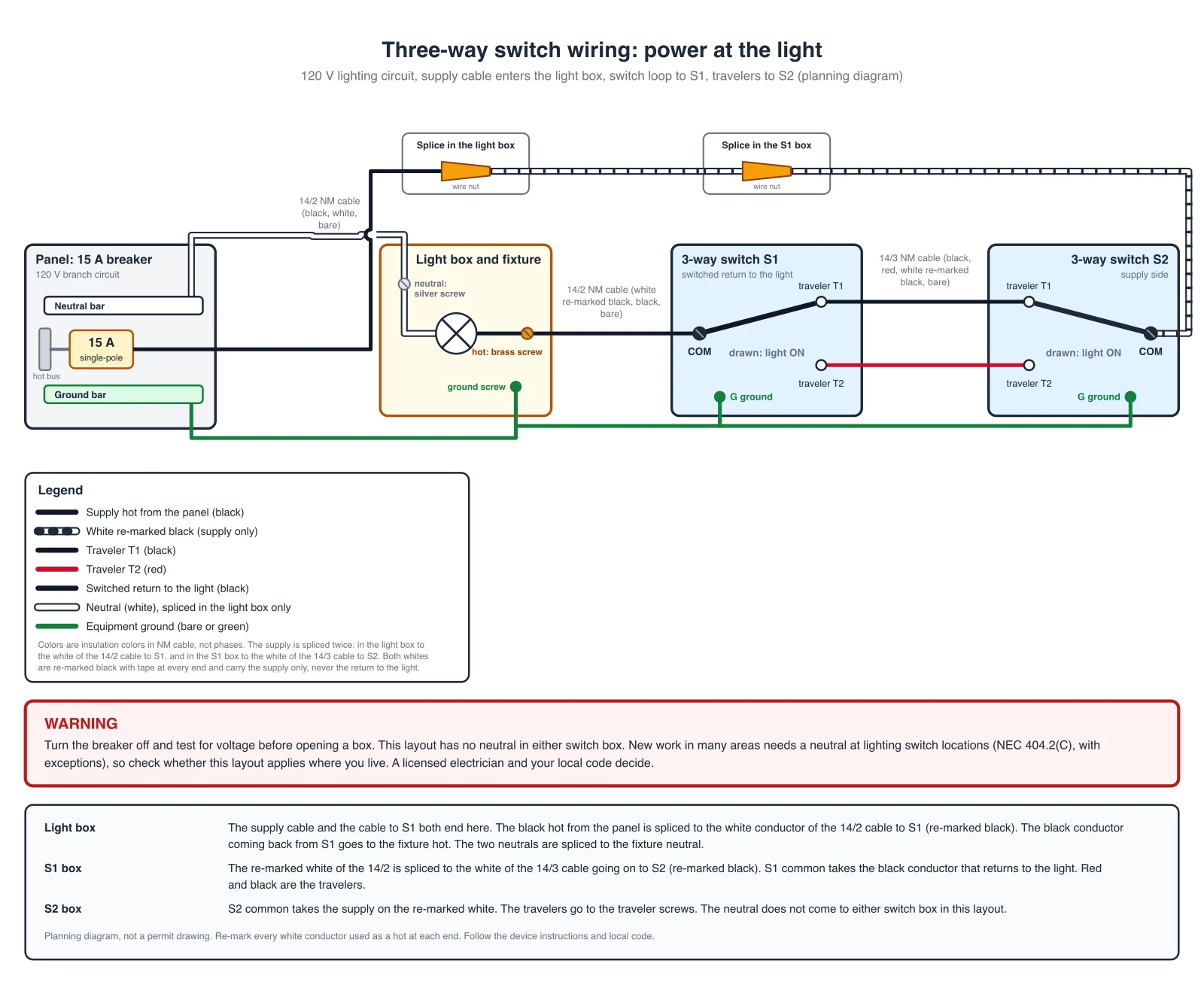
Power at the light, two switches on a switch loop
The supply cable enters the light box. The black hot is spliced there to the white conductor of the 14/2 cable to S1, and in the S1 box to the white conductor of the 14/3 cable to S2. Both whites are re-marked black at every end and carry the supply only. The common of S2 takes that supply. The common of S1 returns on a black conductor to the light. The neutral stays in the light box.
Cable runs: 14/2 from the panel to the light box, 14/2 from the light box to S1, 14/3 between S1 and S2.
Known simplification: the neutral is drawn as one wire from the panel to the light box, where it is spliced to the fixture neutral. The white conductors are drawn with black bands where they are re-marked black. This layout has no neutral in either switch box. New work in many areas needs a neutral at lighting switch locations (NEC 404.2(C), with exceptions), so check whether this layout is allowed for new work where you live.
Connection Table: Common, Travelers, Neutral, Ground
The same connections as the diagrams. Every terminal appears once. The two traveler wires join the traveler terminals of S1 and S2, T1 to T1 and T2 to T2, or crossed, which is equivalent.
| Layout | Connected together |
|---|---|
| power at the first switch |
|
| power at the light (switch loop, white re-marked as the supply) |
|
Colors are insulation colors in NM cable, not phases. Terminal positions differ between makers, so the markings on your switch win.
This page covers one light and two switches. For other wiring, such as home, automotive, or appliance systems, use the Wiring Diagram Maker. For a generator hookup at the panel, see the Generator Transfer Switch Wiring Diagram Builder.
AI illustration of your lighting circuit
Describe a circuit to get a quick picture. AI images can draw wrong connections, so use the exact diagrams and the table above for the real connections and check every common, traveler and neutral of an AI picture.
Generate an AI 3-Way Switch Illustration
Example: Exact reference for this layout (drawn in code, not the AI output)View full sizePreview is free on this page ·
Your three way switch wiring diagram will appear here
AI diagrams are drafts. Check every common, traveler, neutral and ground against the exact diagrams.
Sources (checked October 2026): Purdue Extension 4-H, Wiring Diagrams for 3-Way and 4-Way Switch Combinations, EC&M, The Apprentice's Guide to Article 404 (NEC 404.2), and the installation instructions of 3-way switches from Leviton for the terminal layout. NEC 200.7(C) is described from secondary sources and not quoted.
What a three way switch wiring diagram shows
A three way switch wiring diagram shows how two 3-way switches control one light from two places. Each switch has a common terminal and two traveler terminals. The two travelers join the two switches. The supply hot lands on the common of one switch, and the light is fed from the common of the other. Flipping either switch changes which traveler is live, so the light turns on or off from either place. Electrically it is a single-pole, double-throw switch. This page draws two layouts as exact diagrams from a reviewed connection list, and puts the same connections in a table.
Common and travelers: the part people get wrong
- The common is the one terminal that is different from the other two, and many switch makers mark it with a black or dark screw while the two traveler screws are brass. The leads in the diagrams follow that: supply or light on the common, travelers on the other two. Your switch instructions and the markings on the device decide, not the screw color alone.
- The classic mistake is a traveler on a common. The light then works from one switch only, or only in one position. Wire the common first: one common takes the supply hot, the other common takes the wire that goes to the light. A checker compares each drawing on this page with a reference layout and rejects a drawing that puts the supply or the light on a traveler terminal. It does not see the color of a conductor, so the re-marked white conductors are declared in the netlist and shown in the legend of the diagram, not verified from the drawing.
- Swapping the two travelers at one end is harmless, because the travelers are interchangeable as a pair. Moving a traveler onto a common is not.
Power at the switch or power at the light
- Open the boxes and find where the cable from the panel arrives. If it arrives in a switch box, use the first diagram. If it arrives in the light box, and the light box also holds the cables to the switches, use the second.
- In the second layout the light box is where the supply is split. The hot goes on to the far switch, and the switched wire comes back from the near switch to the fixture. That is why it needs a conductor that is normally white to carry the supply, and why it needs the next section.
- Not covered on this page: a light between the two switches, more than one light, 4-way switches, dimmers and smart switches. Use the Wiring Diagram Maker below for a rough draft of those, and have the layout checked.
The white wire that is not a neutral
- In the power at the light layout the supply is carried to the far switch on the white conductor of the cable, because 14/2 and 14/3 cable have no other conductor to spare. A white conductor used as a hot has to be re-marked, for example with black or red tape, at every point where it ends or is visible. The NEC rule for it (200.7(C)) allows this in a switch loop only for the supply to the switch, and not for the return from the switch to the light. In the diagram the white conductors carry the supply and the black conductor is the return.
- The code text itself is not free to read, and the way it applies to a white conductor used as a traveler is argued among electricians. That is why the diagrams keep the white conductor on the supply and the travelers on black and red. Your local code and your inspector decide.
Neutral at the switch box
In a 3-way circuit the switching is done on the hot conductor (NEC 404.2(A)), so the neutral does not go to the switches in either diagram. The same section says that switch loops do not require a grounded conductor (as quoted by EC&M). Separately, newer editions of the code ask for a grounded conductor at lighting switch locations (404.2(C)), with exceptions, for example where the box can be reached to add a cable. That matters for smart switches, which usually need a neutral, and for new work in areas that have adopted the rule. The two diagrams here show the plain switching circuit only. Ask your local inspector or a licensed electrician what applies where you live.
How to find the common terminal on an old 3-way switch
- Turn the breaker off and confirm with a tester that every wire in the box is dead before you touch anything. Mark the wire on the common terminal with tape before you remove the old switch, so you can put it back on the common of the new one.
- Look at the device first. Many switches have a darker or black screw for the common, and some print COMMON or COM on the body. Compare it with the instructions of the switch if you still have them.
- If there are no markings, remove the switch from the circuit with the power off and the wires disconnected, and use the continuity mode of a multimeter on the loose switch. The common is the terminal that shows continuity to one of the other two in one lever position and to the other in the other position. The two traveler terminals never show continuity to each other. Check both lever positions. This is a bench check on a switch with nothing connected to it, not a test on live wires.
Troubleshooting: what the symptom usually means
- The light works from one switch only: a traveler wire is on the common terminal of one switch, or a common and a traveler are swapped. Turn the power off and compare the switch with the diagram.
- The light is on in some switch positions and off in others, in an order that does not follow the switches: one traveler is not connected at one end, or it is joined to the wrong terminal.
- The light never turns on: the supply is not on a common, or the wire to the light is not on the other common. A loose wire nut, a loose screw or a tripped breaker are the other usual causes.
- The breaker trips when you turn the power on: a hot touches a neutral or a ground, or a traveler is joined to a common. Turn the power off and check every splice.
Smart 3-way switches
Many smart and dimmer replacements for a 3-way circuit need a neutral in the box, and some need a companion device at the other switch. The wiring depends on the product, so follow the instructions that come with the device. Use the diagrams on this page to identify the supply, the light and the travelers, and let the device instructions decide the rest.
Before you open a box
- Turn the breaker off and test every wire for voltage. A 3-way circuit can have more than one live wire in a box, and a switch box can hold wires from another circuit.
- Check how the boxes are wired before you copy a diagram. Many existing circuits do not match a textbook layout, and a layout that works for a new install can be wrong for a house with older wiring.
- Use cable and a breaker sized for the circuit. The diagrams show 14 AWG on a 15 A breaker. Use 12 AWG cable on a 20 A circuit, and match the cable, breaker and switch rating together.
- After wiring, test the light from both switches in all four combinations. If it fails in some combinations, one common and one traveler are swapped.
Exact diagrams vs AI drafts
The two diagrams above are exact reference diagrams. They are drawn in code from a reviewed list of connections, and a checker compares each drawing with a reference table, so the supply and the light always land on the commons, the travelers on the traveler terminals and the neutral never on a switch. We do not show AI-generated wiring images as examples, because image models often draw wrong connections, such as a traveler on a common or a switched neutral. The generator on this page still produces an AI illustration from your prompt. Treat it as a rough picture, compare it with the exact diagrams, and let a licensed electrician decide what gets installed. A diagram from this page is a planning picture. It is not a permit drawing, and it does not replace the device instructions or the electrical code that applies in your area.
Frequently Asked Questions
Related Engineering Tools
 Engineering
Wiring Diagram Maker
Wiring diagrams for home, automotive, appliance, and industrial systems from a plain-English description.
 Engineering
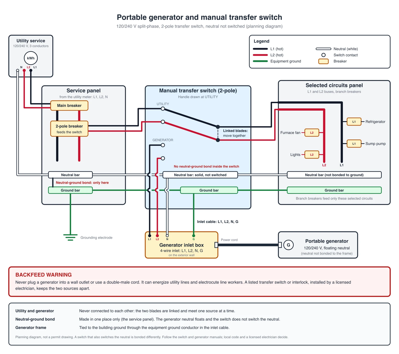
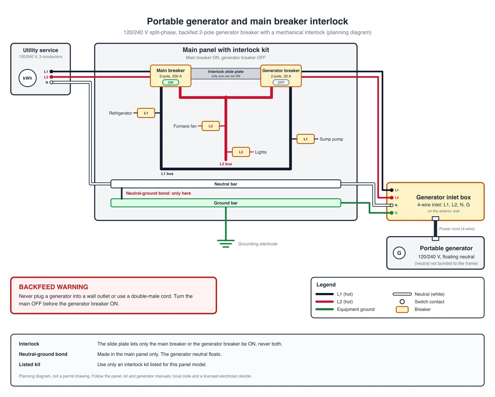
Generator Transfer Switch Wiring Diagram Builder
Manual switch, interlock kit and ATS hookups with exact reference diagrams.
 Engineering
Control Panel Wiring Diagram Generator
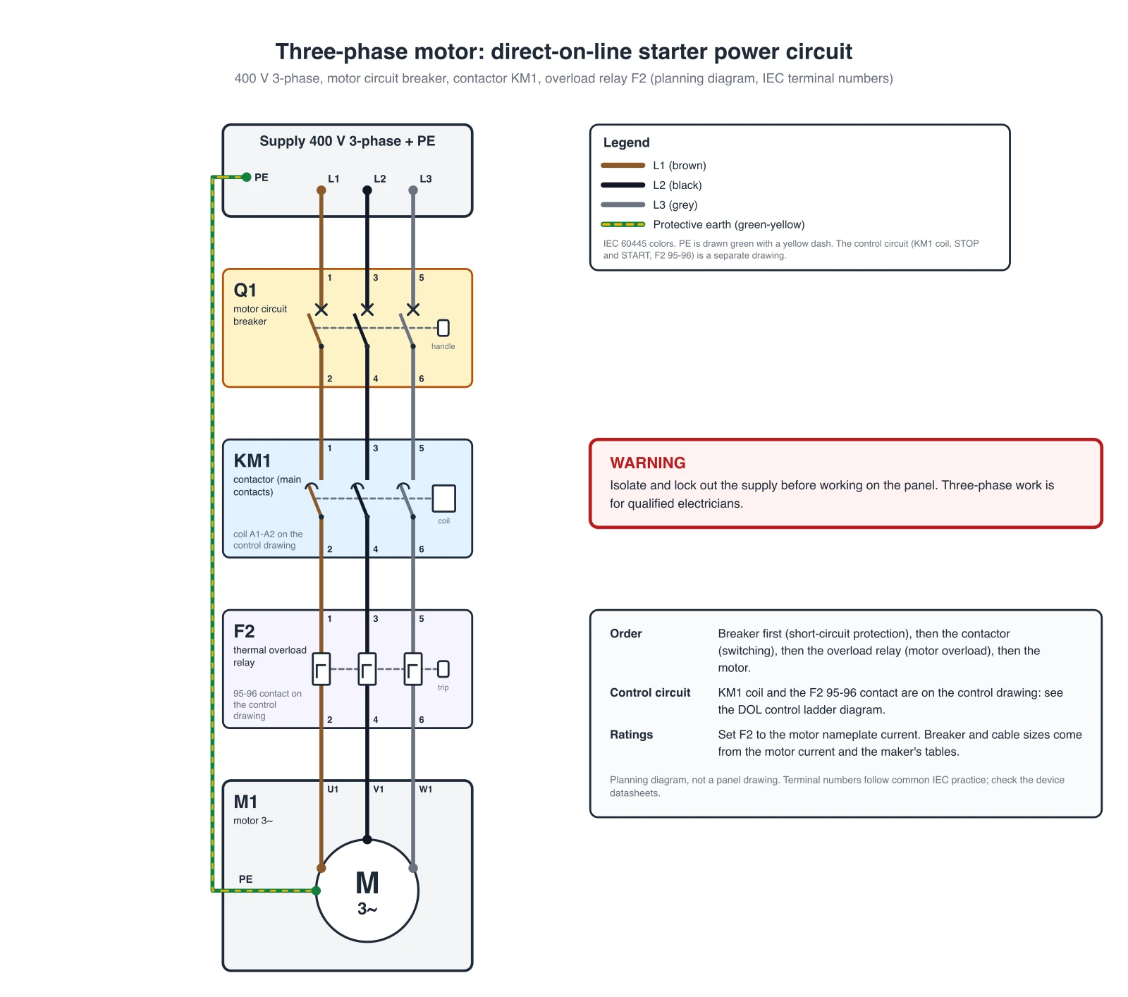
Direct-on-line motor starter power circuit and start/stop ladder diagram, PLC I/O and panel layouts.
 Engineering
Circuit Diagram Maker
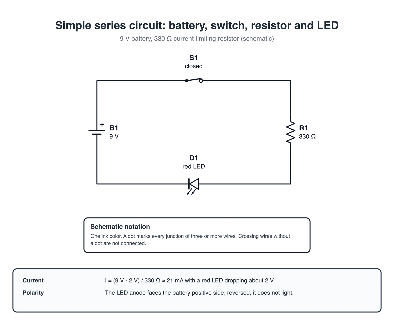
Draw schematic circuit diagrams from a description.