AND gate
Output: 1 only if all inputs are 1
ANSI / IEEE 91
IEC 60617-12
Boolean expression
- Y = A · B
- Y = AB
- Y = A AND B
With the inputs above, Y = 0
| A | B | Y |
|---|---|---|
| 0 | 0 | 0 |
| 0 | 1 | 0 |
| 1 | 0 | 0 |
| 1 | 1 | 1 |
Chart of AND, OR, NOT, NAND, NOR, XOR, XNOR and buffer symbols in ANSI/IEEE and IEC styles, with Boolean expressions, truth tables, PNG, SVG and print.
Try the inputs
Set A and B once. Every card below highlights the matching truth table row and shows the output.
NOT and BUFFER have one input and use A only.
Output: 1 only if all inputs are 1
ANSI / IEEE 91
IEC 60617-12
Boolean expression
With the inputs above, Y = 0
| A | B | Y |
|---|---|---|
| 0 | 0 | 0 |
| 0 | 1 | 0 |
| 1 | 0 | 0 |
| 1 | 1 | 1 |
Output: 1 if any input is 1
ANSI / IEEE 91
IEC 60617-12
Boolean expression
With the inputs above, Y = 1
| A | B | Y |
|---|---|---|
| 0 | 0 | 0 |
| 0 | 1 | 1 |
| 1 | 0 | 1 |
| 1 | 1 | 1 |
Output: inverts the input
ANSI / IEEE 91
IEC 60617-12
Boolean expression
With the inputs above, Y = 0
| A | Y |
|---|---|
| 0 | 1 |
| 1 | 0 |
Output: 0 only if all inputs are 1
ANSI / IEEE 91
IEC 60617-12
Boolean expression
With the inputs above, Y = 1
| A | B | Y |
|---|---|---|
| 0 | 0 | 1 |
| 0 | 1 | 1 |
| 1 | 0 | 1 |
| 1 | 1 | 0 |
Output: 1 only if all inputs are 0
ANSI / IEEE 91
IEC 60617-12
Boolean expression
With the inputs above, Y = 0
| A | B | Y |
|---|---|---|
| 0 | 0 | 1 |
| 0 | 1 | 0 |
| 1 | 0 | 0 |
| 1 | 1 | 0 |
Output: 1 if the inputs differ
ANSI / IEEE 91
IEC 60617-12
Boolean expression
With the inputs above, Y = 1
| A | B | Y |
|---|---|---|
| 0 | 0 | 0 |
| 0 | 1 | 1 |
| 1 | 0 | 1 |
| 1 | 1 | 0 |
Output: 1 if the inputs match
ANSI / IEEE 91
IEC 60617-12
Boolean expression
With the inputs above, Y = 0
| A | B | Y |
|---|---|---|
| 0 | 0 | 1 |
| 0 | 1 | 0 |
| 1 | 0 | 0 |
| 1 | 1 | 1 |
Output: passes the input through
ANSI / IEEE 91
IEC 60617-12
Boolean expression
With the inputs above, Y = 1
| A | Y |
|---|---|
| 0 | 0 |
| 1 | 1 |
All eight gates on one landscape page: ANSI and IEC symbols side by side, Boolean expressions and truth tables. Download it or print it for a lab bench or a revision sheet.
Scroll sideways on small screens. Downloads are 2828 by 2000 px PNG or scalable SVG.
Any Boolean function can be built from NAND gates alone, or from NOR gates alone, which is why chips and teaching kits stock so many of them. The trick is the inverter: tie both inputs of a NAND or NOR together and it becomes a NOT gate. Each example below is two gates in a chain, and the table next to it is computed from the circuit, then compared row by row with the gate it should equal.
The first NAND gives (A · B)′. The second NAND has both inputs tied to that signal, so it acts as a NOT and restores A · B.
| A | B | n | Y | AND |
|---|---|---|---|---|
| 0 | 0 | 1 | 0 | 0 |
| 0 | 1 | 1 | 0 | 0 |
| 1 | 0 | 1 | 0 | 0 |
| 1 | 1 | 0 | 1 | 1 |
Y matches the AND column on all 4 rows
The first NOR gives (A + B)′. The second NOR has both inputs tied together, so it inverts that signal and gives A + B.
| A | B | n | Y | OR |
|---|---|---|---|---|
| 0 | 0 | 1 | 0 | 0 |
| 0 | 1 | 0 | 1 | 1 |
| 1 | 0 | 0 | 1 | 1 |
| 1 | 1 | 0 | 1 | 1 |
Y matches the OR column on all 4 rows
A truth table lists every combination of input values and the output each one produces. With two inputs there are four rows, and with n inputs there are 2 to the power n rows. Every table on this page is computed in code by running the gate’s Boolean function over all input combinations, not typed in, so the rows always match the expression shown next to it. Use the A and B buttons above the cards to see one row light up on every gate at once. For example, with A = 1 and B = 0, AND gives 0, OR gives 1, XOR gives 1 and NAND gives 1.
Each card lists the common ways to write the gate’s function: a dot or no sign for AND, a plus sign for OR, a prime or the ¬ sign for NOT, and ⊕ for XOR. Two identities connect the gates. The NAND of A and B equals NOT A OR NOT B, and the NOR of A and B equals NOT A AND NOT B. These are De Morgan’s laws, and they are why a NAND gate is drawn as either an AND with a circle on the output or an OR with circles on the inputs in some diagrams. Both forms mean the same thing.
A set of gates is universal if every Boolean function can be built from it. NAND alone is universal, and so is NOR alone. Tying the two inputs of a NAND together gives a NOT. A NAND followed by that NOT gives AND. Feeding inverted inputs into a NAND gives OR. NOR works the same way with the roles of AND and OR swapped. This is why many logic families, and many exam questions, ask you to rebuild a circuit using only one gate type. The two worked examples above are drawn and checked by the page itself.
Symbols are drawn from scratch for this page after the standards IEEE Std 91-1984 with supplement 91a-1991, and IEC 60617-12 (binary logic elements, now kept in the IEC 60617 database). The standards themselves are not reproduced. IEC also defines "=" as the equivalence qualifier (output 1 when all inputs are equal). For two inputs it matches "=1" with an output circle, which is how XNOR is drawn here, but with three or more inputs the two differ, so this chart sticks to the two-input form. The chart covers the eight basic gates with one or two inputs. Gates with more inputs, flip-flops, multiplexers and other IEC elements are outside its scope.
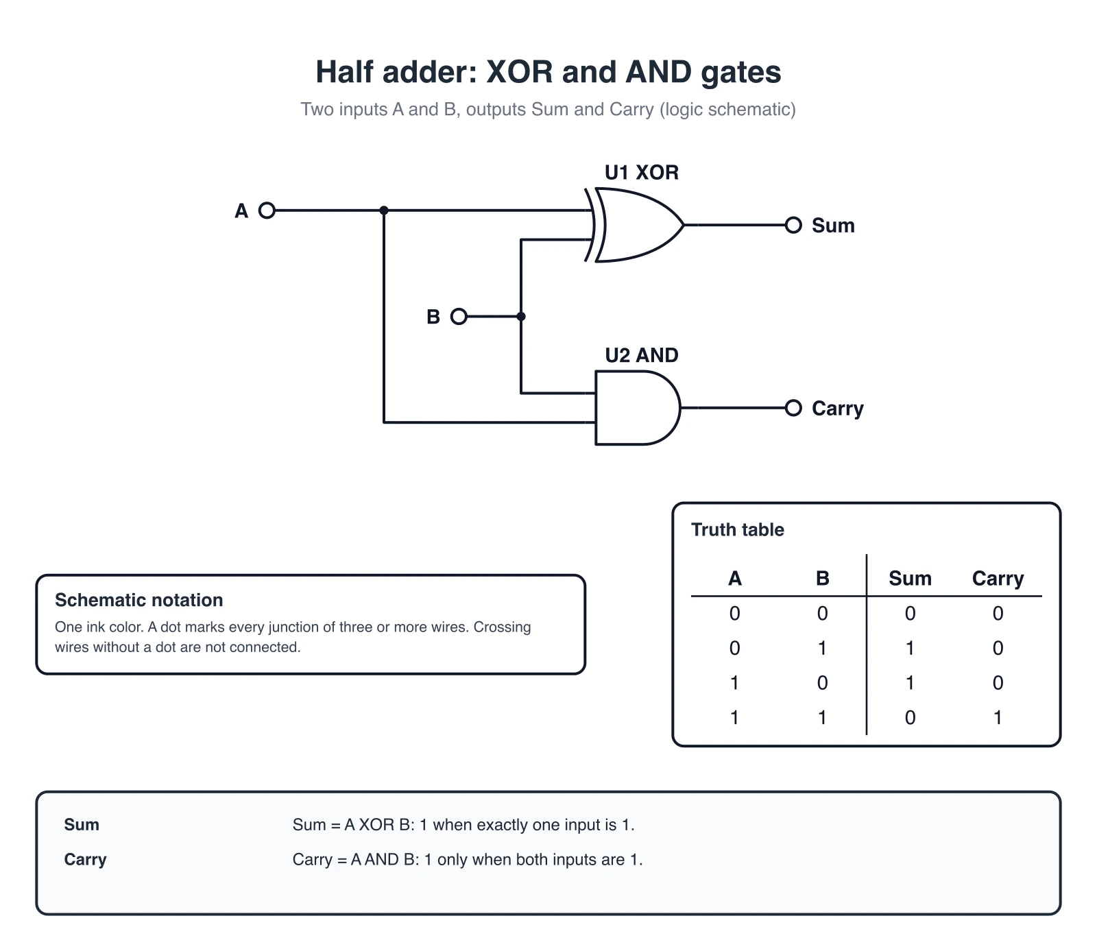 Electronics
Draw schematics with standard symbols, including logic circuits such as a half adder with its truth table.
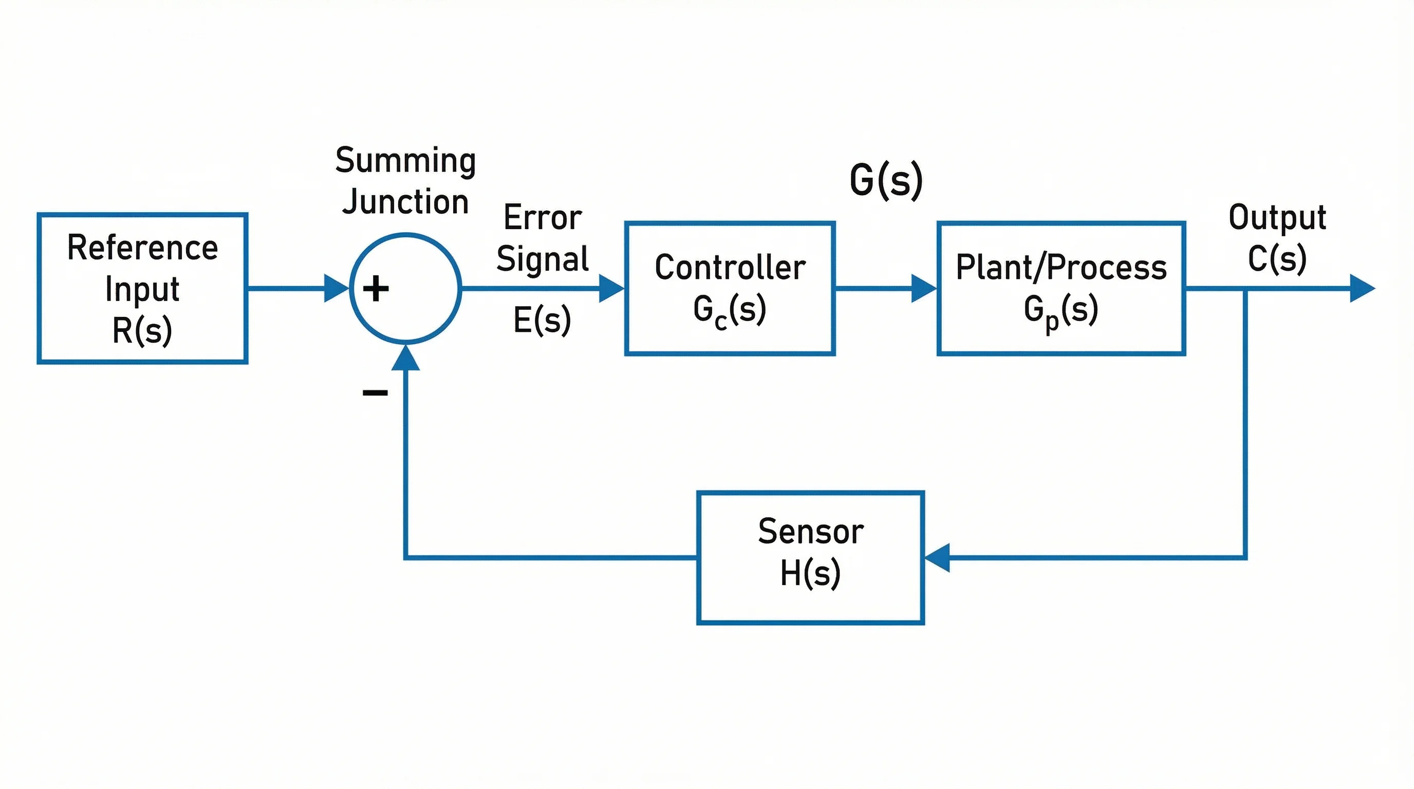 Engineering
Create block diagrams for control systems, signal paths and system architecture.
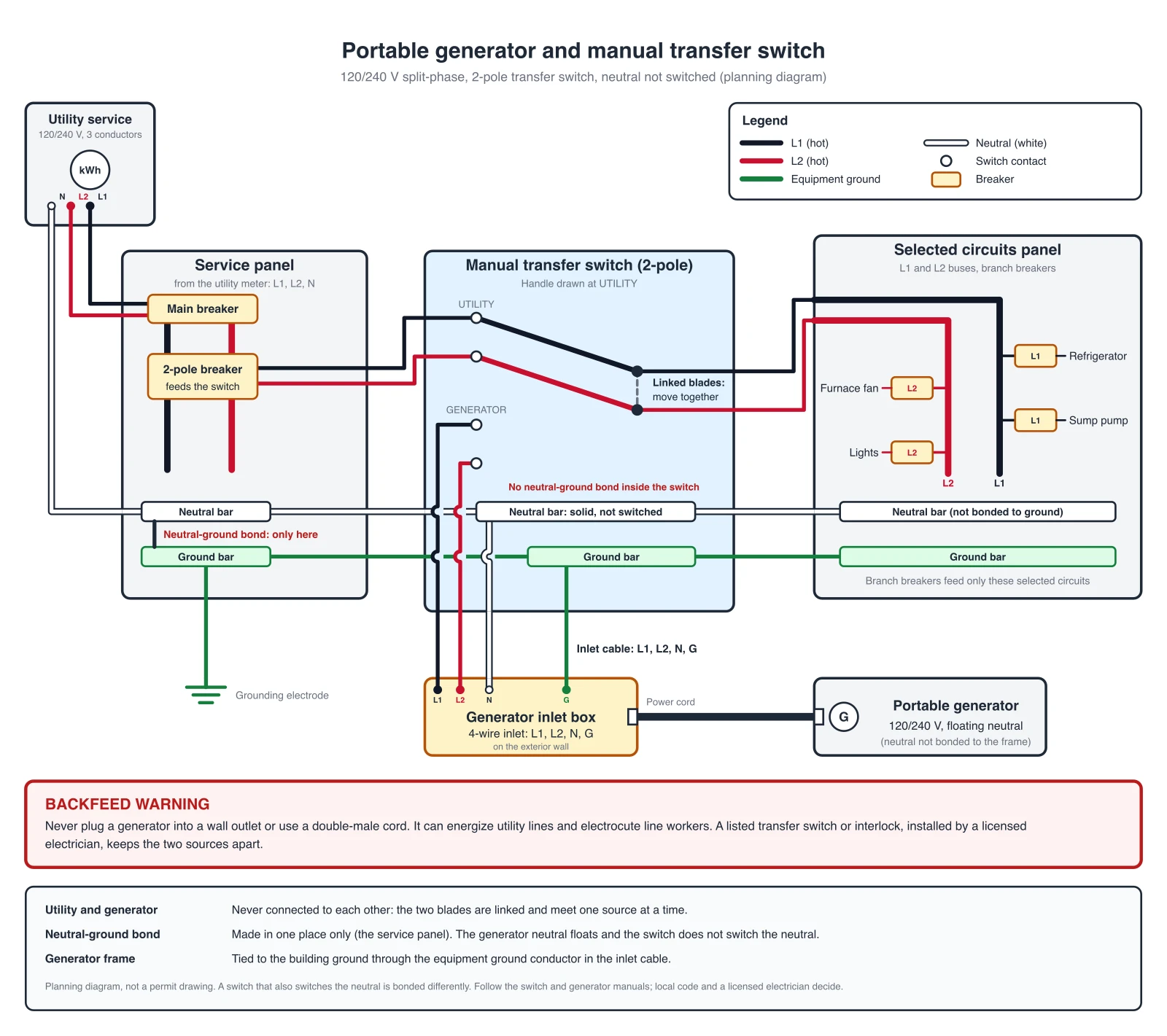 Electrical
Generate labeled wiring diagrams for electrical installations and equipment.