Wiring Diagram Maker for Electrical Wiring Diagrams
Make a wiring diagram with AI. Describe the system — components, terminals, wire colors, and connections — and get a clean electrical wiring diagram for home, automotive, or appliance projects. Download as PNG.
AI Wiring Diagram Maker
Free to try ·
Your wiring diagram will appear here
Describe components, terminals, wire colors, and connections
Wiring Diagram Examples
Home, automotive, appliance, and industrial wiring diagrams
Home Electrical Wiring
A whole-house layout — panel, branch circuits, outlets, switches, and the ground and neutral bus bars.
Automotive Wiring
A 12V vehicle system with color-coded wires — battery, alternator, starter, fuses, lights, and grounds.
Industrial Control Panel
A control-panel layout with a PLC, contactors, motor starters, overloads, and an emergency-stop circuit.
HVAC System Wiring
An appliance-style diagram with the thermostat terminals and both low- and high-voltage wiring.
Lighting Circuit
Single-pole, 3-way, and dimmer switches wired to fixtures, with hot, neutral, and ground shown.
Three-Phase Motor
A star-delta motor starter — contactors, timer, overload, and the U1/V1/W1 terminal connections.
What is a wiring diagram?
A wiring diagram is a drawing that shows the actual electrical connections between the components of a system — which wire runs from which terminal to which terminal. It maps the physical layout: every component, every connection point, and often the wire colors and gauges, so you can build, troubleshoot, or repair the wiring exactly as drawn. Unlike a block sketch, a wiring diagram is meant to be followed wire by wire, which is what this generator draws — labeled components, terminals, and connections on a clean white background.
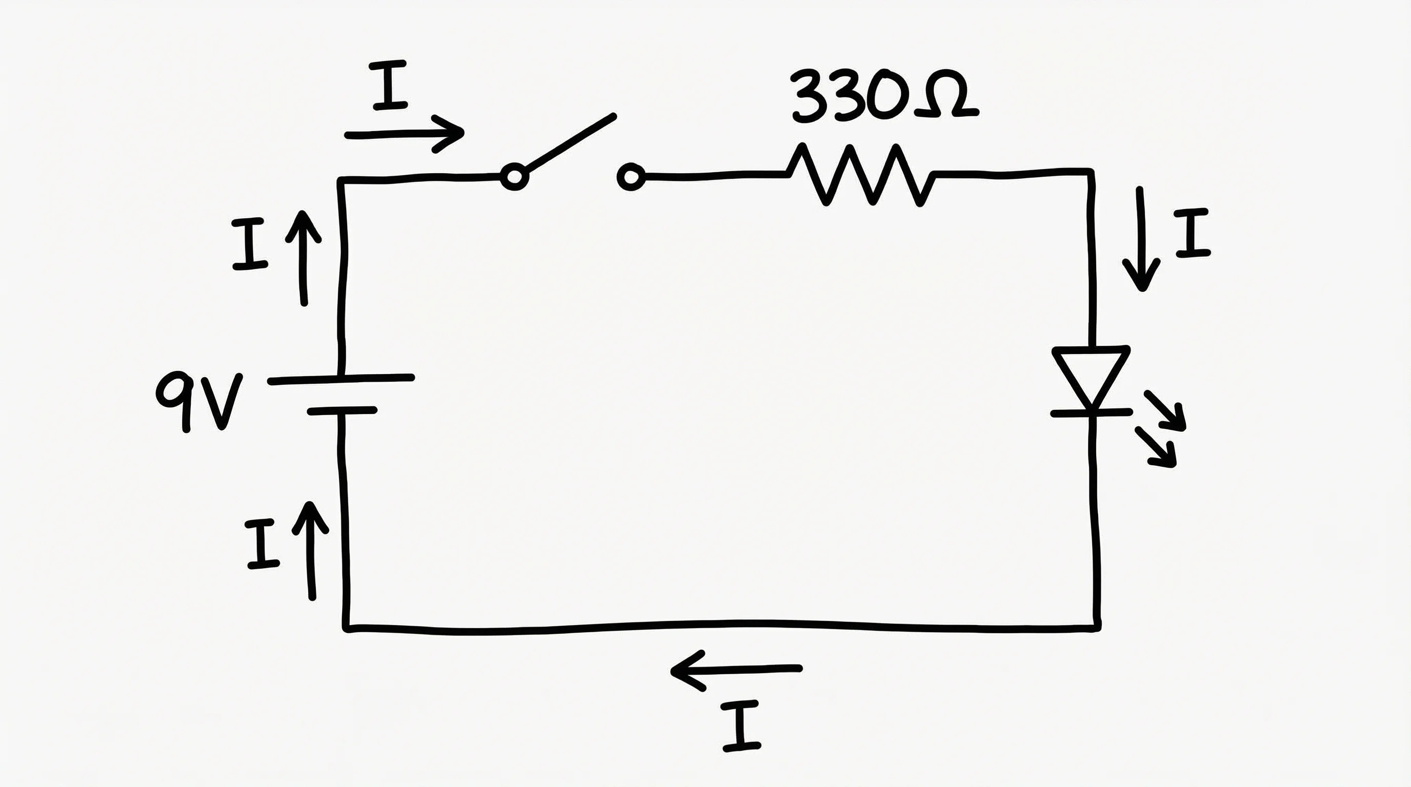
Wiring diagram vs circuit schematic
A wiring diagram and a circuit schematic describe the same system in two different ways. A schematic is abstract: it uses standardized symbols to show how a circuit works electrically, ignoring where parts physically sit or how wires are routed. A wiring diagram is physical: it shows the real components, their terminals, the wire colors, and the literal connections between them — the picture you use to assemble or trace the wiring. Use a schematic to understand the logic of a circuit, and a wiring diagram to actually wire it. If you need the symbolic, theory-level view instead, our circuit diagram maker focuses on schematic symbols and circuit behavior.
Components and connections a wiring diagram shows
- Components: the power source, switches, outlets, motors, relays, fuses or breakers, lights, transformers, and control devices.
- Terminals: the labeled connection points on each component (for example a thermostat’s R, Y, G, and W terminals, or a motor’s U/V/W).
- Wires: the conductors between terminals, often drawn or labeled with their color (black hot, white neutral, green or bare ground) and gauge.
- Protective devices: fuses, circuit breakers, and overload relays placed in the line they protect.
- Grounds and commons: ground and neutral connections, which keep the system safe and give every device a return path.
Where wiring diagrams are used
Wiring diagrams are the working reference across home electrical, automotive, and appliance projects. In a house, they map the panel, branch circuits, outlets, and switch loops so an installation matches code. In a vehicle, a 12V wiring diagram traces the battery, alternator, starter, fuse box, lights, and grounds — essential when chasing a fault. For appliances and HVAC, they show how a thermostat, transformer, contactor, and motors connect, and on the plant floor a control-panel diagram lays out PLCs, contactors, and motor starters. Anywhere wires connect components, a wiring diagram is how people build and fix it.
How to make a wiring diagram from a description
Describe the system in plain language — the components, the terminals, the wire colors, and how everything connects — and the tool draws a labeled wiring diagram. The more specific you are, the more accurate the result: name the parts ("12V battery, alternator, starter solenoid"), the connections ("ignition switch feeds the starter relay"), and any color or terminal conventions you want shown. Generate a few options, pick the clearest, adjust the description if a connection is wrong, and download the diagram as a PNG for your notes, manual, or build sheet.
Reading and verifying a wiring diagram
To read a wiring diagram, start at the power source and follow each wire to its terminal, checking the color and the component it lands on; trace the return path through neutrals or grounds back to the source. Confirm protective devices sit in the right line and that switches break the intended conductor. AI-generated diagrams are a fast way to draft, study, or document wiring, but treat them as a reference draft rather than a code-compliant plan — for real home or automotive electrical work, always follow your local electrical code and consult a licensed electrician before connecting power.
Frequently Asked Questions
Related Engineering Tools
 Engineering
Circuit Diagram Maker
Draw circuit schematics with standard symbols to show how a circuit works electrically.
 Engineering
Schematic Diagram Maker
Create technical schematic diagrams for systems, equipment, and processes.
 Engineering
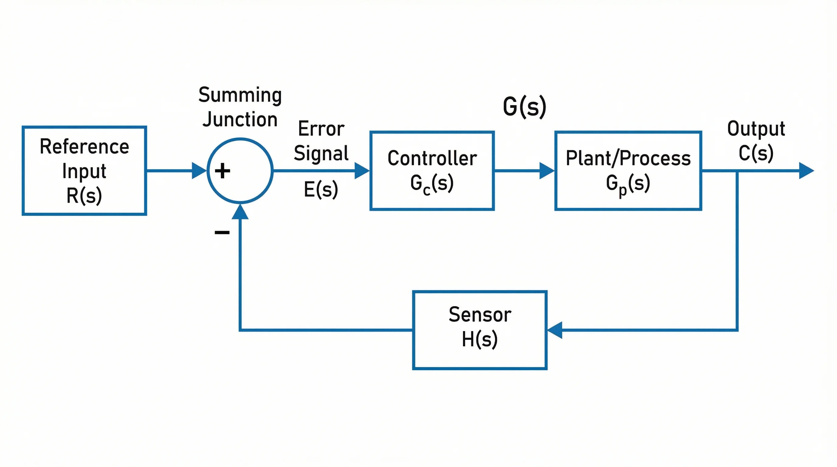
Block Diagram Generator
Map systems as labeled blocks and signal flows for a high-level overview.