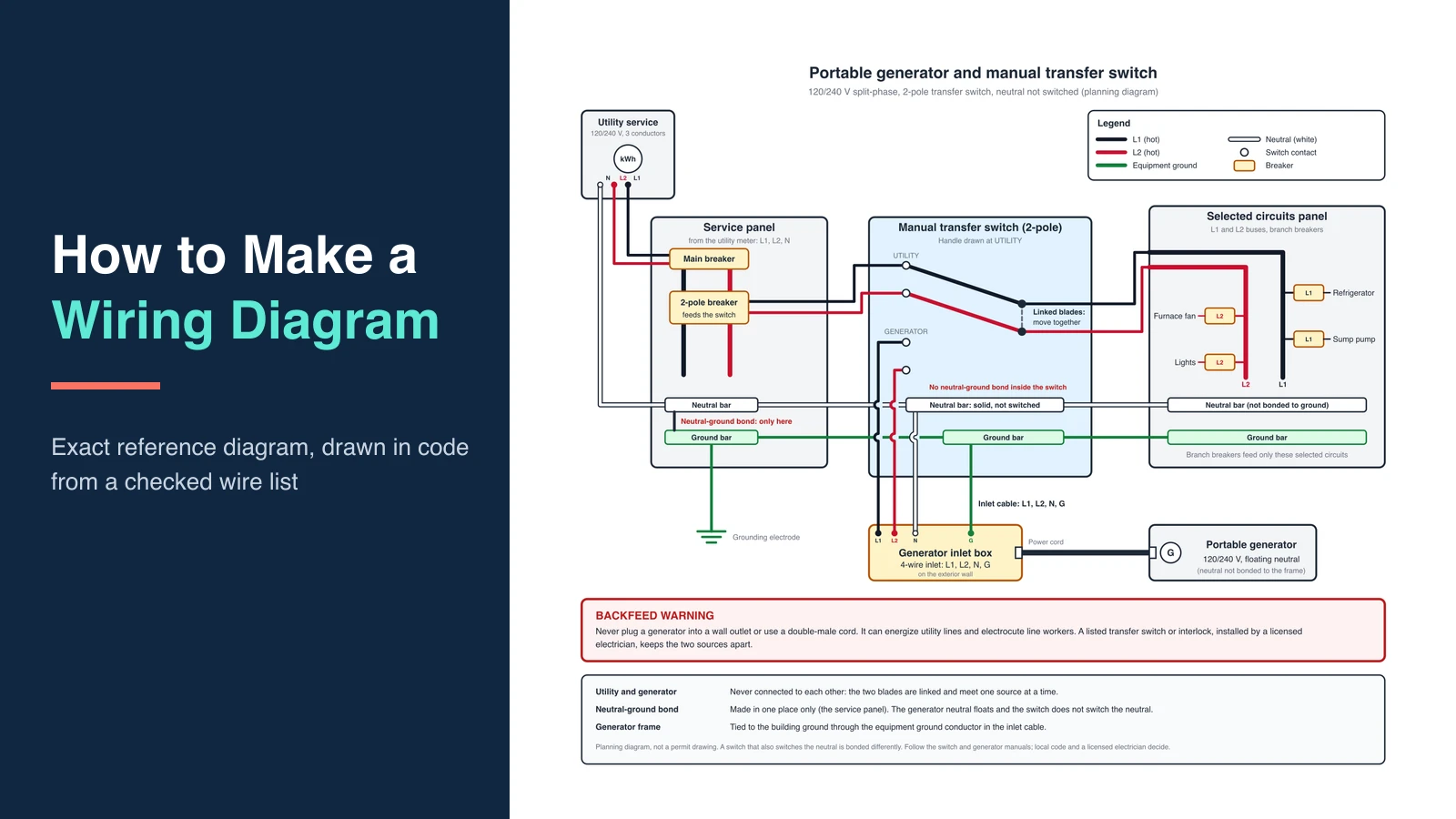
How to Make a Wiring Diagram: Step-by-Step for Engineers
Learn how to make a wiring diagram: pick IEC or ANSI symbols, number every wire, and avoid the mistakes that fail shop reviews. A practical engineer workflow.
A wiring diagram is a map of physical conductors: which terminal on which device gets which wire. If you came here from a software roundup, you are in the wrong article — that comparison lives in Best Electrical Wiring Diagram Software 2026. This page is the method: how to make a wiring diagram that a panel builder, a reviewer, or a future you can land a meter on.
The short version: pick one symbol standard, freeze a tag scheme, draw power before control, number every wire, and never let a pretty schematic substitute for the manufacturer’s terminal diagram.
Wiring Diagram Maker
Describe a circuit in plain language and get a first-pass wiring diagram. Use it for drafts, teaching, and client review — not as a stamped as-built.
Draft a wiring diagram →Wiring diagram vs schematic vs single-line
People search “how to make a wiring diagram” and then draw a schematic. Those are different documents. Mixing them is how field techs land on the wrong terminal.
| Drawing | Question it answers | What it hides |
|---|---|---|
| Single-line (one-line) | How does power flow at a system level? | Extra conductors, control wires, most terminals |
| Schematic (elementary) | How does the function work? Which contact opens which coil? | Physical routing, wire colors, terminal block positions |
| Wiring diagram (connection / point-to-point) | Which terminal is landed on which wire? | Abstract function (unless you also keep a schematic) |
| Panel layout | Where does the hardware sit on the backpan? | Electrical function |
You often need both a schematic and a wiring diagram. The schematic is for understanding. The wiring diagram is for landing. AutoCAD Electrical, EPLAN, and shop packages treat them as related sheets, not synonyms. For a science-lab apparatus schematic (not electrical landing), see How to Make a Schematic Diagram. For a power-system overview, use a single-line diagram.
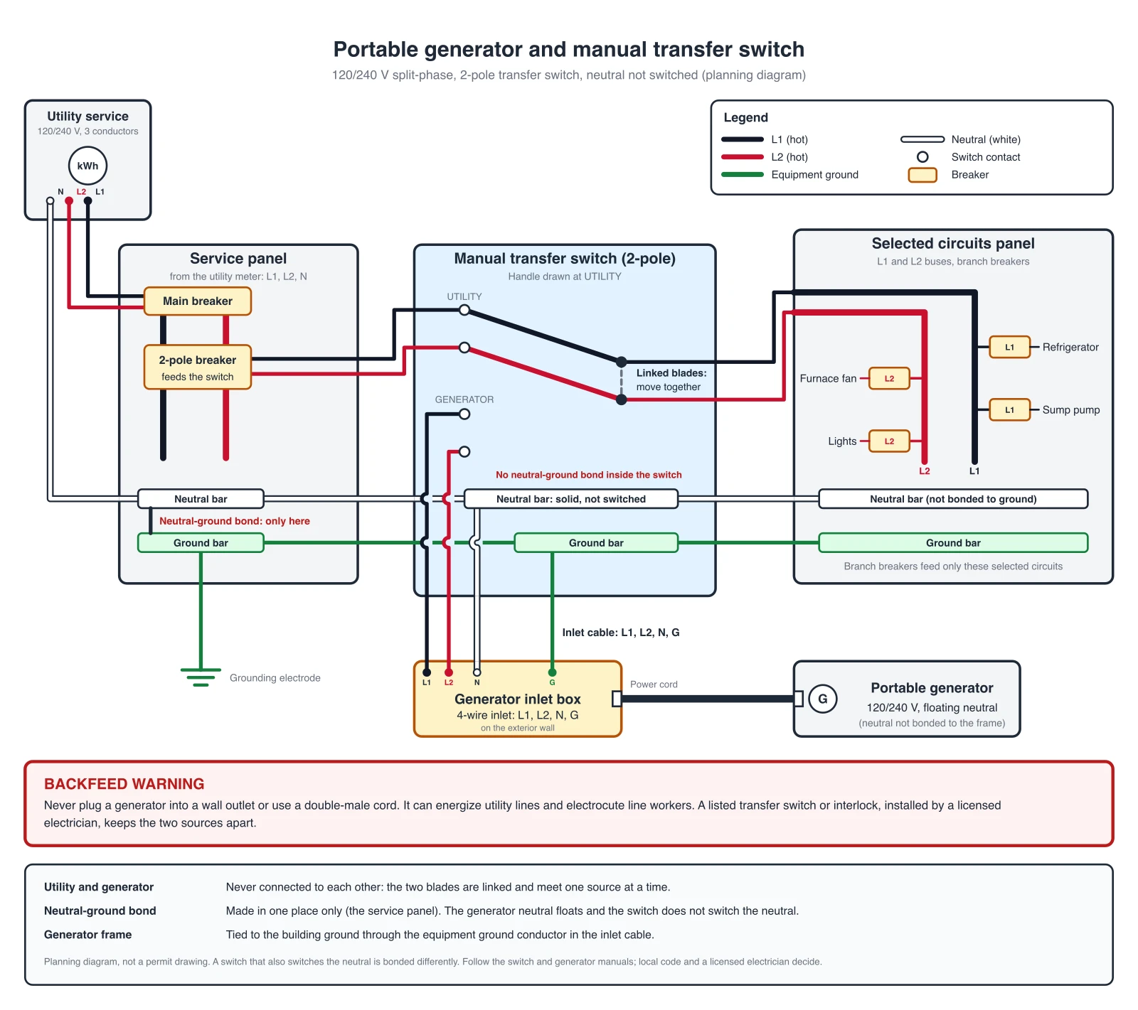
An exact diagram, drawn in code from a checked wire list. A wiring diagram shows devices and conductors and says which conductor is switched or bonded. It is not a pictorial of the enclosure and not a one-line of the facility.
Step 1 — Write the job before you draw a line
Open a notes file, not a CAD sheet. Answer these in one paragraph:
- What is being wired? Motor starter, lighting circuit, HVAC controller, vehicle harness, PLC panel.
- Who uses the drawing? Shop, field service, AHJ, customer, students.
- Which standard governs symbols? IEC 60617 (most of the world, export machinery) or IEEE 315 / ANSI Y32.2 and NFPA 79 practice (North American industrial controls). Record the choice in the title block.
- What voltage and environment? 24 VDC control vs 480 VAC power changes wire size, color, and whether you may mix circuits on one drawing without a clear hierarchy.
- Is this a design, a shop drawing, or an as-built? Design can be slightly abstract. As-built must match the panel.
If you cannot name the governing standard, stop. A drawing that mixes IEC coils (rectangles) with ANSI coils (circles) will pass a slide deck and fail a design review. Comparison charts such as ANSI vs IEC electrical symbols are useful for reading other people’s drawings. They are not permission to mix libraries on yours.
Step 2 — Collect the source documents
A wiring diagram copied from memory is a liability. Gather:
- One-line or load list (motors, heaters, feeders)
- Control narrative or cause-and-effect (what the circuit does)
- Manufacturer terminal diagrams and datasheets for every PLC card, drive, relay, and operator device
- Cable schedule if the job already has one
- Existing panel photos or as-builts if this is a revision
The schematic tells you that coil K1 drops when E-stop is hit. The datasheet tells you that the coil is on A1/A2 and the NC contact you need is 21-22, not 11-12. Field mistakes start here, not in line weight.
Step 3 — Freeze tags, wire numbers, and the title block
Do this before the first conductor.
Device tags. Pick one scheme and keep it for the project:
- IEC-style reference designations (IEC 81346 families:
-Qbreakers,-Kcontactors,-Ffuses,-Sswitches,-Ttransformers,-Xterminals) - Or North American device tags (
M1,CR1,FU1,PB1) plus IEEE C37.2 device numbers on protection drawings
Do not invent a third language mid-project.
Wire numbers. Every conductor that can be landed gets a unique number. Common shop rules:
- Change the wire number when the conductor goes through a device that can open (a contact, a fuse, a PLC output)
- Keep the number through a terminal block that is only a landing
- Put the wire number on both ends and on the drawing next to the line
Title block, on every sheet, not just sheet 1:
- Project, drawing number, revision, date, drawn-by / checked-by
- Governing symbol standard and voltage
- Sheet index (“sheet 3 of 7 — motor starter M2”)
- Legend or a pointer to the legend sheet
If a reviewer cannot find the revision, they will treat the PDF as untrusted.
Step 4 — Draw in this order (not the order you think of the problem)
A reliable sequence for industrial and building controls:
- Incoming power and isolation — disconnect, fusing, grounding/PE, control-power transformer.
- Safety / E-stop — drawn so a reader can see the safety path without hunting.
- Power circuit — contactors, overloads, motors, heaters. Heavier line weight than control.
- Control circuit — coils, auxiliary contacts, selector switches, interlocks.
- PLC / controller I/O — one wire per point, with the actual card terminal IDs from the manufacturer.
- Signals and networks — analog loops, Ethernet, fieldbus. These are easy to leave off and expensive to add in the field.
- Terminal strips and inter-panel cables — the point of a wiring diagram.
Leave empty space. Never route a conductor through a tag. Never stack four labels on one node.
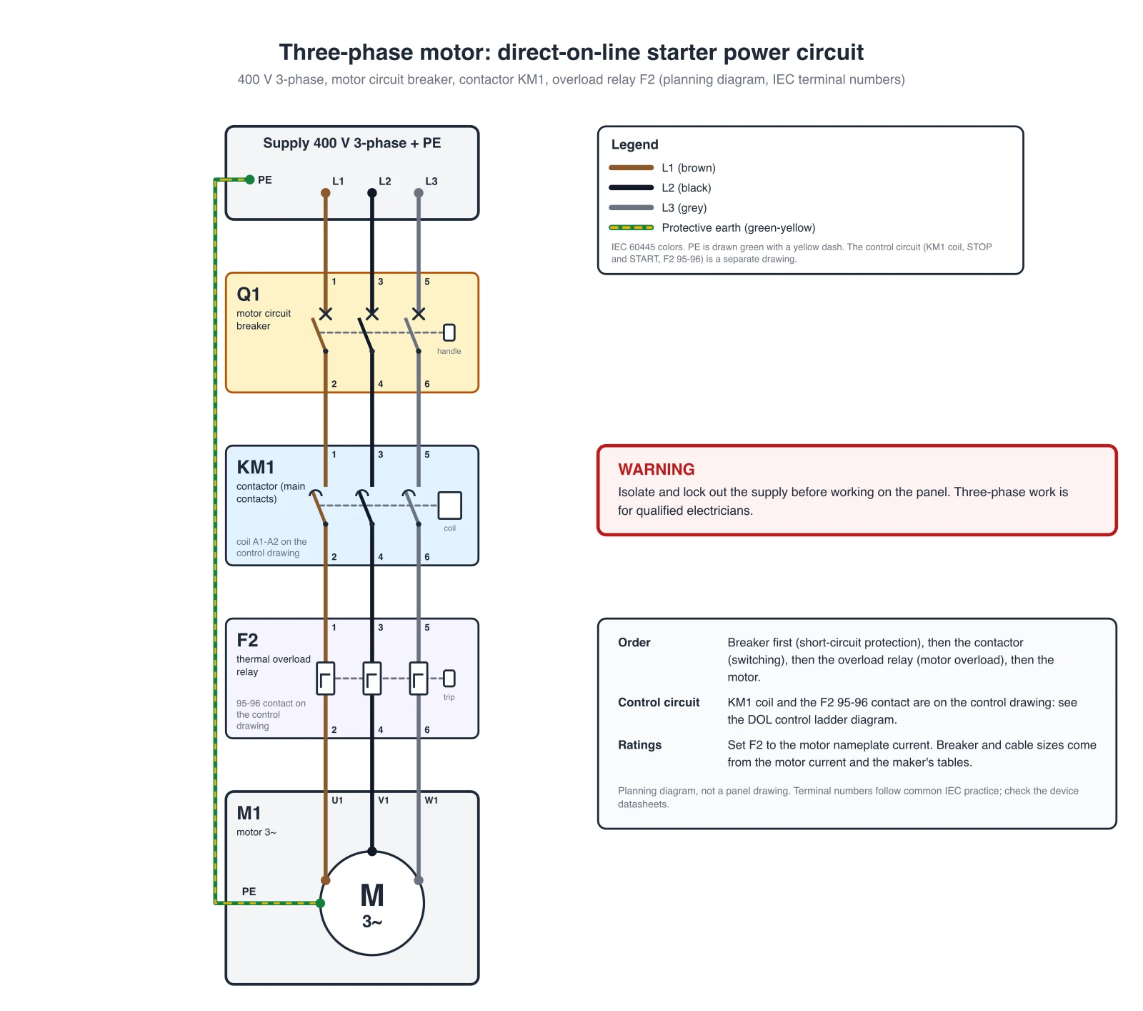
The power sheet first, drawn in code: supply, breaker, KM1 main contacts, overload relay, motor. It has no coil, STOP or START on it. Those go on the control sheet below.
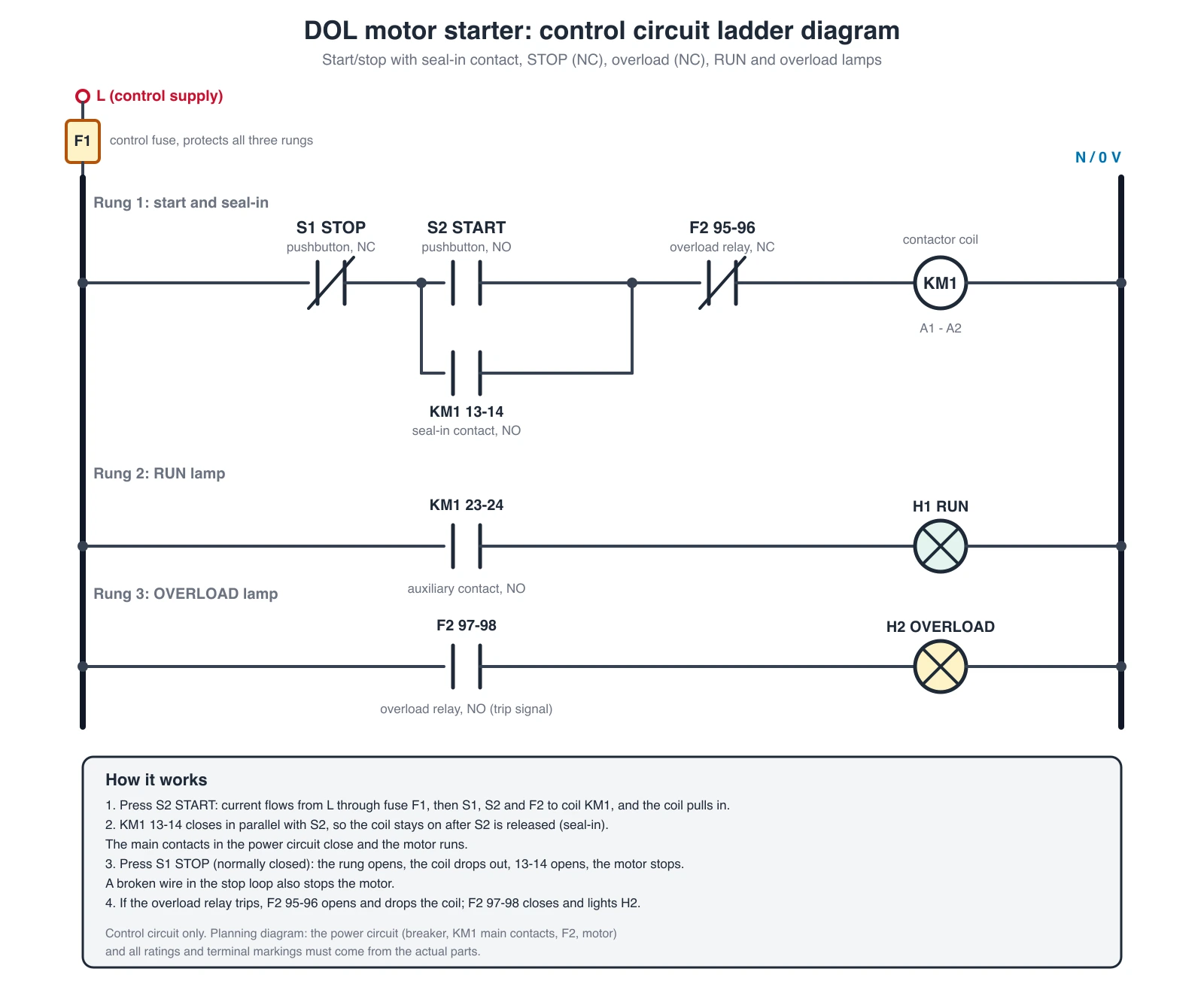
The matching control circuit, drawn in code. It covers control only: the KM1 coil and the F2 95-96 contact from the power sheet above. Either sheet alone is a schematic fragment, not a wiring diagram.
Step 5 — Apply one symbol library, then build the legend
Rules that prevent the most common redlines:
- One library per project. IEC or ANSI/IEEE. AutoCAD Electrical and EPLAN both let you lock a catalog; lock it.
- Orientation does not change meaning. A rotated symbol is still that device. Do not invent a “sideways = different function” rule.
- Symbols are not to scale. Size them for readability at the printed sheet size (usually 11×17 / A3 for shop packs).
- Split devices must cross-reference. If a relay coil is on sheet 2 and a contact is on sheet 5, both locations show the other sheet.
- Put ratings next to the symbol when they matter: fuse amps, wire gauge, coil voltage, motor kW/HP and FLA.
Then build a legend that lists every distinct symbol you actually used. A 200-symbol IEEE poster in the appendix does not help a tech at 2 a.m. A 24-row legend of this job’s devices does.
For electronics-style component symbols (resistors, ICs) rather than industrial landing, the circuit diagram maker is the closer tool. Do not put DIP-switch art on a motor starter sheet.
Step 6 — Number terminals the way the hardware is numbered
This is the step that separates a teaching cartoon from a shop drawing.
- Use the manufacturer’s terminal IDs (
A1,13/14,DI0.0,COM,PE), not “left screw.” - Show wire color if the job spec or regional code requires it (IEC 60446 / local electrical code for power and PE; company standard for 24 VDC).
- Show cable IDs when more than one multi-conductor cable leaves the enclosure (
W12 / 4×1.5 mm² + PE). - If two devices share a COM, draw the jumper. Implied commons are how miswires happen.
Cross-check every coil and contact against the datasheet before you issue revision 0. The drawing is wrong if the hardware cannot be landed as shown — even if the function is correct.
Step 7 — Check the drawing like a reviewer, not like the author
Walk these failure modes. They are the ones that show up in real redlines:
| Check | Failure mode |
|---|---|
| Uniqueness | Two devices tagged K1, or two wires numbered 103 |
| Standard purity | IEC rectangle coil next to an ANSI circle coil |
| Hierarchy | Control wires drawn as heavy as 480 V |
| Safety path | E-stop drawn as a suggestion, not a circuit |
| Orphans | A device in the BOM with no landing; a landing with no BOM item |
| Revision | “Final” PDF with no rev cloud and no date |
| Print test | Labels vanish at 11×17; you designed on a 4K monitor |
| As-built vs design | Field changed a terminal and the PDF did not |
Read the drawing out loud: “Wire 211 leaves PLC output Q0.2, lands X2:14, continues to valve solenoid YV2 terminal 1, returns on 212 to 0 V.” If you cannot say that sentence, a tech cannot either.
Step 8 — Issue the pack, then maintain as-builts
A usable issue is more than one PNG:
- PDF of all sheets, latest revision in the filename
- Source file (DWG, EPLAN project, or the editable native)
- Cable / wire list if the shop pulls from a schedule
- Updated BOM
When the panel is built, redline the PDF the same day. An as-built that lags the enclosure is worse than no drawing: people will trust it.
A 30-minute first draft (when you do not have CAD yet)
Engineers often need a diagram before the EPLAN project exists: a kickoff slide, a student lab, a customer “is this what you meant?”, a grant figure. CAD is the wrong first tool for that job.
- Write the narrative in five bullets (power in → protect → switch → load → return).
- List devices and the terminals you already know.
- Generate a first-pass diagram from that list.
- Print it and mark every terminal that is still generic.
- Move the survivors into CAD or a shop package.
Wiring Diagram Maker
Turn a device-and-terminal list into a readable first draft you can redline.
ConceptViz will not replace AutoCAD Electrical, EPLAN, or a PE stamp. It will not size conductors, apply a local electrical code, or produce a permit set. Use it when the bottleneck is getting a readable draft on the page. Move to CAD when the bottleneck is landing, BOM, and revision control.
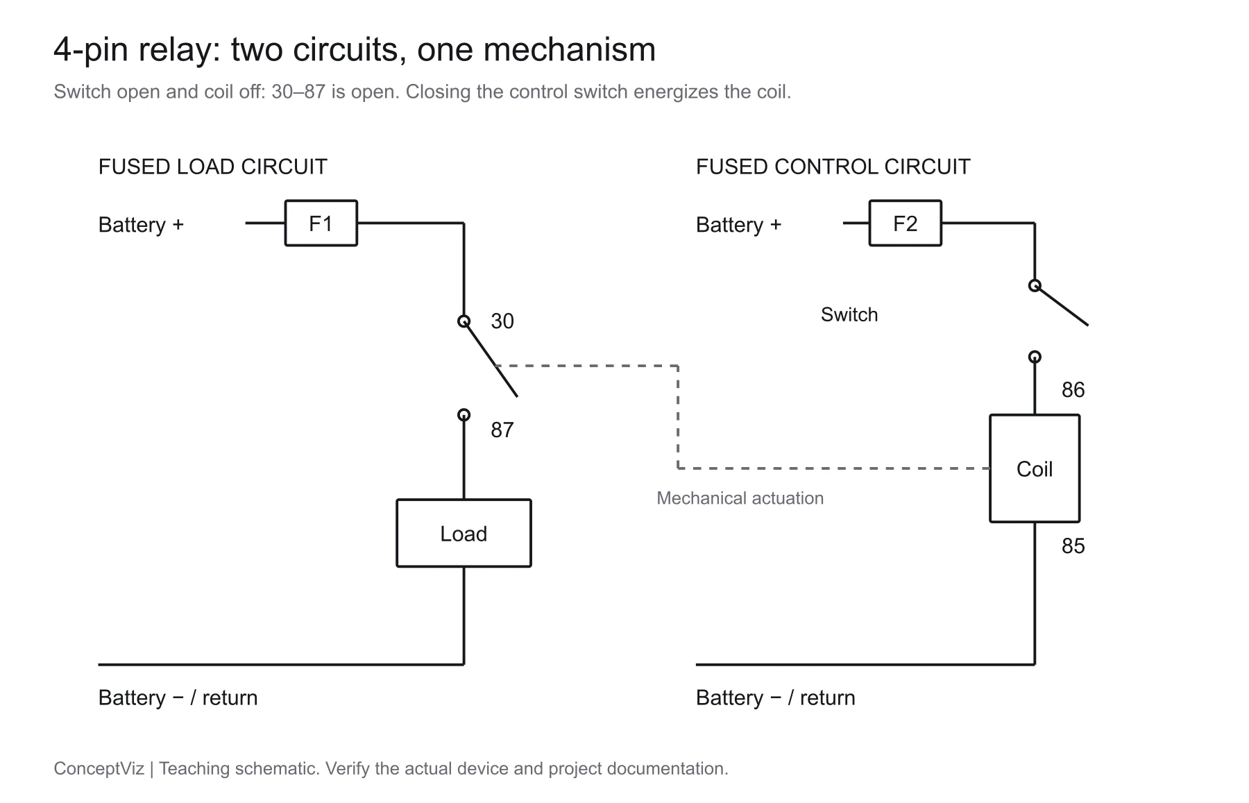
An exact 4-pin relay circuit, drawn in code. Harness drawings follow the same method: unique wire IDs, connector pin-outs, and one symbol language, even when the symbols look different from a motor starter.
Home, HVAC, and automotive: same method, different codes
The search “how to make a wiring diagram” also covers homeowners and technicians. The method above still holds. The authority changes:
- Dwelling work in the United States is an NEC / AHJ problem. A web diagram is not a permit. If you are not the licensed electrician of record, treat any generated home diagram as a conversation sketch.
- HVAC drawings must match the equipment installation manual. Thermostat “R, C, G, Y, W” labels are not optional art.
- Automotive diagrams live or die on connector views and cavity numbers, not on pretty coil symbols.
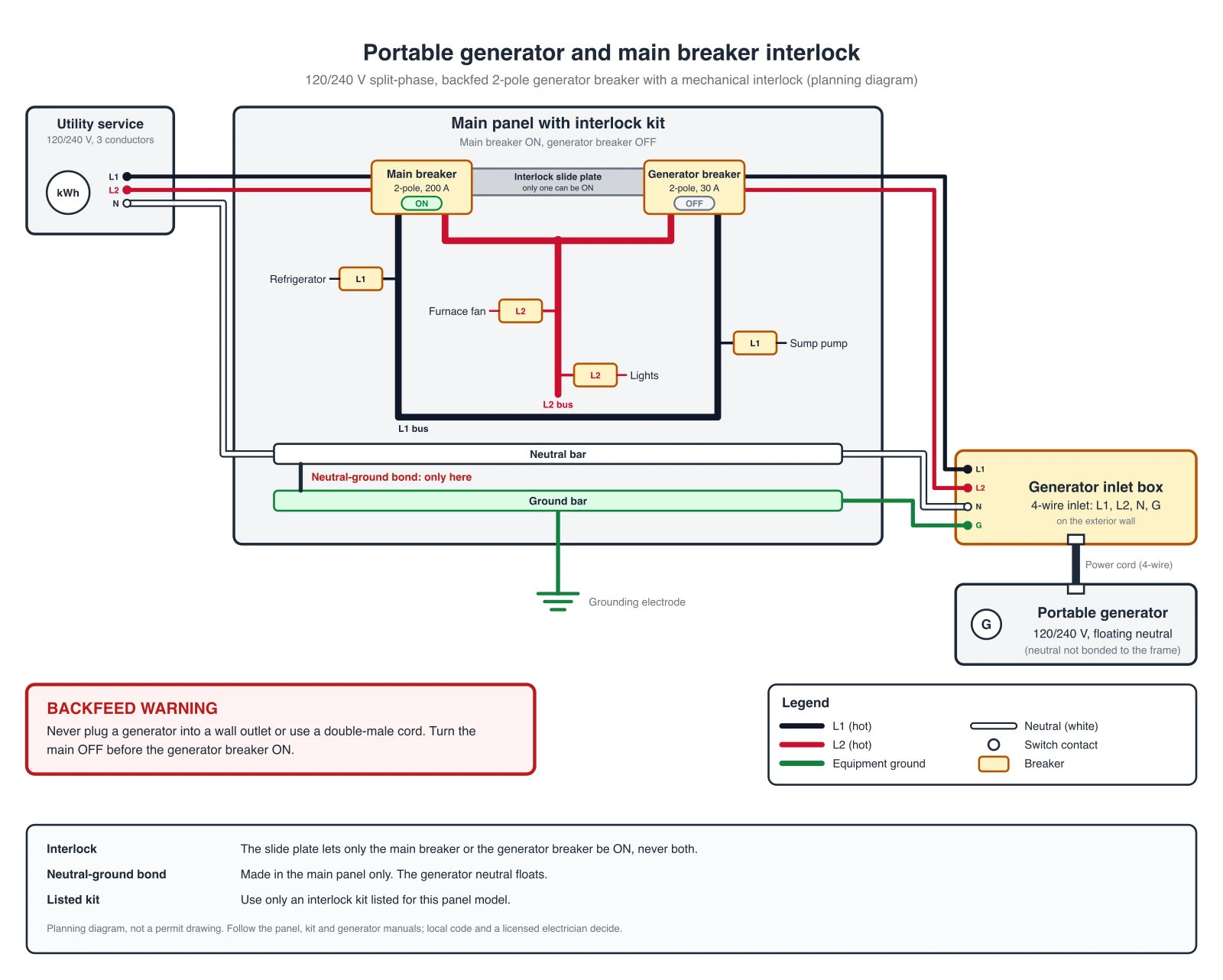
An exact house-panel diagram of a generator interlock, drawn in code. A diagram like this can teach a circuit. It is not a substitute for a licensed electrical drawing or an inspection.
Common mistakes (and the fix)
- Drawing a schematic and labeling it “wiring.” Fix: add terminal IDs or admit it is a schematic.
- Mixing IEC and ANSI on one sheet. Fix: pick one; rebuild the legend.
- No wire numbers. Fix: number before you pretty the layout.
- Coil voltage missing. Fix: write
K1 24 VDCnext to the coil. A 120 VAC coil on a 24 V drawing is a smoked part. - Implied grounds. Fix: show PE / GND landings.
- Copy-paste from a previous job without changing tags. Fix: unique tags per project, then a search for leftovers.
- Trusting an AI or template for as-built. Fix: every landing against the datasheet and the panel.
If you want software recommendations after the method is clear — symbol libraries, collaboration, price — go back to the wiring diagram software guide.
Frequently Asked Questions
What is a wiring diagram?
A wiring diagram shows physical connections: which conductor lands on which terminal of which device. It is different from a schematic, which shows electrical function, and from a single-line diagram, which shows system-level power flow.
How do I make a wiring diagram from scratch?
Write the job and governing symbol standard, collect datasheets, freeze device tags and wire numbers, draw power then control then I/O, label every terminal, and check the print at shop size. Then issue a revision-controlled PDF.
Should I use IEC or ANSI symbols?
Use the standard the end user or region requires. IEC 60617 is common on export machinery and outside North America. IEEE 315 / NFPA 79 practice is common on North American industrial controls. Never mix the two libraries on one drawing.
What is the difference between a wiring diagram and a schematic?
A schematic explains how the circuit functions. A wiring diagram explains how to land the wires. Shops build from wiring diagrams and terminal plans; troubleshooters often need both.
Do I need CAD software to make a wiring diagram?
For issued shop drawings, permit sets, and as-builts, yes — use electrical CAD so tags, cross-references, and BOMs stay consistent. For a kickoff draft, teaching figure, or client review, a faster generator is enough if you verify terminals afterward.
Can I use an AI-generated wiring diagram on a job site?
Not as the issued drawing. Treat generated diagrams as drafts. Confirm every terminal against the manufacturer diagram, apply the project standard, and move the result into your revision-controlled CAD or shop package before anyone lands a wire.
What must appear on every sheet?
Title block (project, drawing number, revision, date), governing standard, voltage, a legend or a pointer to it, unique device tags, and unique wire numbers. Safety circuits should be readable without hunting across unmarked sheets.
Is a home wiring diagram enough to do my own electrical work?
No. Dwelling electrical work is governed by local code and usually requires a licensed electrician and an inspection. A diagram you make online is a planning sketch, not a permit.
Bottom line
Making a wiring diagram is a documentation job dressed up as drawing. Standard, tags, wire numbers, and manufacturer terminals decide whether the sheet is useful. Software only decides how fast you can issue the next revision.
If you need a readable first pass today, start on the wiring diagram maker, redline the terminals, then promote the survivors into CAD. If you are still choosing tools rather than drawing, use the software comparison instead of this page.
Categories
More Posts

How to Create a Conceptual Framework for Your Research Paper: Complete Guide
Learn how to develop a strong conceptual framework for your thesis or dissertation, with step-by-step instructions, examples, templates, and diagram tips.
Protein Structure: The 4 Levels Explained Simply
Protein structure made simple: the four levels (primary, secondary, tertiary, quaternary), the bonds that stabilize each, and why structure decides function.

How to Draw a Neural Network Architecture Diagram: A Complete Guide
Learn how to draw neural network architecture diagrams for CNNs, RNNs, Transformers, and more. A step-by-step guide with tools, examples, and best practices.