Battery Wiring Diagram Generator with Fuse, Switch, and Shunt
Generate a battery wiring diagram from a text prompt: main fuse, switch, shunt, series or parallel banks, DC-DC charging. With exact reference diagrams.
Create Your Battery Wiring Diagram
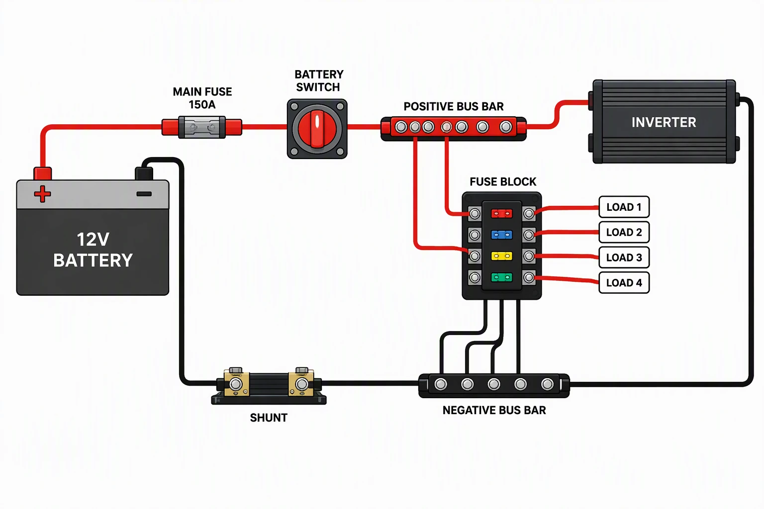 Example: Battery, main fuse, switch, shunt, inverterView full size
Preview is free on this page ·
Your battery wiring diagram will appear here
AI diagrams are drafts. Check every connection, fuse, and polarity before use.
Battery Wiring Diagram Examples
Three exact reference diagrams drawn in code, plus two AI diagrams with their known flaws noted. AI diagrams need human review.
Batteries in series vs parallel (exact diagram)
Drawn in code, not by AI. Series links the positive of one battery to the negative of the next, so voltages add and amp-hours stay the same. Parallel joins positive to positive and negative to negative, so voltage stays the same and amp-hours add. Both layouts store the same energy, 2,400 Wh in this example.
Main fuse, battery switch, and shunt (exact diagram)
Drawn in code. Battery positive goes through the main fuse, then the battery switch, then a positive bus bar with one fuse per branch. All negatives return to the negative bus bar, and the main negative cable runs through the shunt back to the battery. Ratings and cable sizes are left off on purpose.
Starter and house battery with a DC-DC charger (exact diagram)
Drawn in code. The alternator charges the starter battery. The DC-DC charger takes power from the starter battery through a fuse near that battery and charges the house battery through a second fuse near the house battery, so the house loads cannot drain the starter battery. Both batteries and the charger return to one negative bus bar.
Battery with inverter and shunt (AI diagram)
AI-generated from the prompt shown. We checked it: red positive and black negative are correct, the main fuse is the first device after the battery positive, and the shunt sits in the negative path. Known flaws: the image prints a 150A main fuse rating that is not tied to any load or wire size, so do not copy it; the main fuse is drawn mid-run instead of close to the battery positive; the inverter has no dedicated fuse of its own (it needs one sized to its cable, close to the bus bar); the load negative returns are not drawn; and the fuse block wiring is inconsistent. Treat it as a draft to correct.
Starter and house battery with DC-DC charger (AI diagram)
AI-generated from the prompt shown, after earlier attempts put the charger input cable on the starter battery negative terminal; the prompt now says which terminal sits where. This version has correct polarity and a fuse on each charger cable. Known flaws: no fuse ratings, no protection drawn at the alternator, and no ignition-switched signal for chargers that need one.
For boat electrical systems, see the Boat Wiring Diagram Generator. For other wiring diagrams, use the Wiring Diagram Maker. To compare tools, read 12 best wiring diagram software and apps, and for drawing conventions see how to make a wiring diagram.
What a battery wiring diagram shows
A battery wiring diagram shows how one or more batteries are connected to each other and to the loads: which terminal each cable leaves from, what fuse or breaker protects it, what switch can cut it, and how the current returns to the negative side. The same battery-bank pattern appears in boats, vans, workshops, and off-grid cabins; this page stays on the battery bank itself. Describe your batteries and parts in the prompt box, generate a draft, and compare it with the exact reference diagrams in the gallery above.
Single battery: the order of parts
- Battery positive goes first to the main fuse, placed as close to the battery positive terminal as practical. The fuse protects the cable that runs away from the battery, so every unprotected centimeter of that cable is a risk.
- Next comes a battery switch or disconnect, which lets you isolate the system for maintenance or storage.
- A positive bus bar then splits power into branches. Each branch gets its own fuse sized for its cable and load, and a large load such as an inverter follows its maker’s fuse and cable instructions.
- On the negative side, the battery negative goes to a shunt if you use a battery monitor, and every negative load and charger connects on the load side of the shunt. Nothing else attaches to the battery negative post, or the monitor will miss that current.
- The main fuse must be rated to interrupt the battery’s short-circuit current, not only to carry the load. Lithium batteries can deliver very high fault current, so check the interrupt rating on the fuse and use the battery maker’s fuse guidance.
Series vs parallel: voltage or capacity
- Series connects the positive of one battery to the negative of the next. Voltages add and amp-hours stay the same: two 12V 100Ah batteries make 24V 100Ah.
- Parallel connects positive to positive and negative to negative. Voltage stays the same and amp-hours add: the same two batteries make 12V 200Ah.
- Both layouts store the same energy, 2,400 Wh here. Pick series when the equipment needs a higher voltage, and parallel when you need more run time at the same voltage.
- Use matching batteries (same type, voltage, capacity, and age) and follow the maker’s limit on how many can be linked. In larger banks, cable length from each battery to the common point should be as even as practical so the batteries share current evenly.
Two batteries: DC-DC charger, isolator, or combiner
- A dual battery setup keeps one battery for starting the engine and another for the loads, so a flat house battery does not leave you stranded.
- A DC-DC charger takes power from the starter battery or alternator and charges the house battery with a profile suited to its chemistry. The input cable is fused near the starter battery and the output cable near the house battery, each sized to the charger and the cable, and a negative return to the common negative bus. Some chargers also need an ignition-switched signal; follow the maker’s instructions.
- A battery isolator or a voltage-sensing combiner is a simpler alternative that links the batteries while the engine runs and separates them when it stops. It does not change the charge profile for the house battery, so check that your battery chemistry accepts what the alternator supplies.
Fuse, cable, and voltage drop
Size the fuse to protect the cable, and size the cable from the load current, the length of the round trip, and the voltage drop you can accept. The longer the run, the heavier the cable. Use the cable and fuse tables from the equipment maker rather than a gauge printed on a generated picture; generated diagrams can print wrong or mismatched gauges and ratings, which is why the diagrams on this page leave cable sizes off. Crimp lugs properly, use stranded copper cable, and keep the battery terminals from carrying anything but the main cables.
Marine battery wiring: what changes on a boat
Marine battery wiring uses the same building blocks with stricter habits. Boat batteries are usually fused at the positive terminal, switched with a battery switch (a 1-2-BOTH-OFF selector on dual battery boats), and wired with stranded, tinned marine cable, because the environment is damp and the engine space vibrates. Positive is conventionally red and negative black or yellow. ABYC E-10 and E-11 are the primary reference standards for US boats, and E-11 limits how far the main overcurrent device can sit from the battery, so check the current edition. The boat wiring diagram generator covers bilge pumps, fuse blocks, and outboard systems in full.
Which rules apply to your installation
There is no single rule for every battery installation. On boats in the United States, ABYC E-10 (storage batteries) and E-11 (AC and DC systems) are the primary reference standards, and ISO 13297 covers electrical systems on small craft elsewhere; check the current edition and your country’s rules, and see our boat wiring page for the marine side. Do not assume that the building wiring code applies to a vehicle’s DC system. For a vehicle, a stationary battery bank, or any other system, follow the battery, charger, and inverter makers’ instructions and the rules where you live, and have a qualified electrician review anything you install.
How to generate a battery wiring diagram from text
- List the parts you actually have: battery or batteries with voltage and chemistry, main fuse, switch, shunt, bus bars, inverter or chargers, and each load.
- State the order of the positive path and say where the negative returns go. For two batteries, say which terminal each cable leaves from.
- Ask for red positive wires, black negative wires, short labels, and generic components with no brand names.
- Generate, then check every connection against your own system: polarity, fuse position, and shunt position first.
- Re-prompt to fix anything wrong. If a cable ends on the wrong terminal, say which terminal it should use.
Exact diagrams vs AI illustration on this page
The three exact diagrams are drawn in code, so every wire and label is placed on purpose. The two AI diagrams were generated from the prompts shown. We checked each one for polarity, fuse position, shunt position, symbols, and label spelling, and their captions list the flaws we found. Our first AI attempts at the dual battery and the series and parallel layouts had wrong terminals, such as a charger input cable on the negative terminal and a jumper that shorted one battery, so we did not use them; the series and parallel comparison is an exact diagram for that reason. AI output is useful for a quick layout draft, but it can leave out a connection, put a fuse in the wrong place, or land a cable on the wrong terminal. A diagram from this page is a planning sketch. It is not a traced schematic or a wire list, and it does not replace the equipment makers’ instructions, the applicable standard, or a qualified electrician.
Frequently Asked Questions
Related Engineering Tools
 Engineering
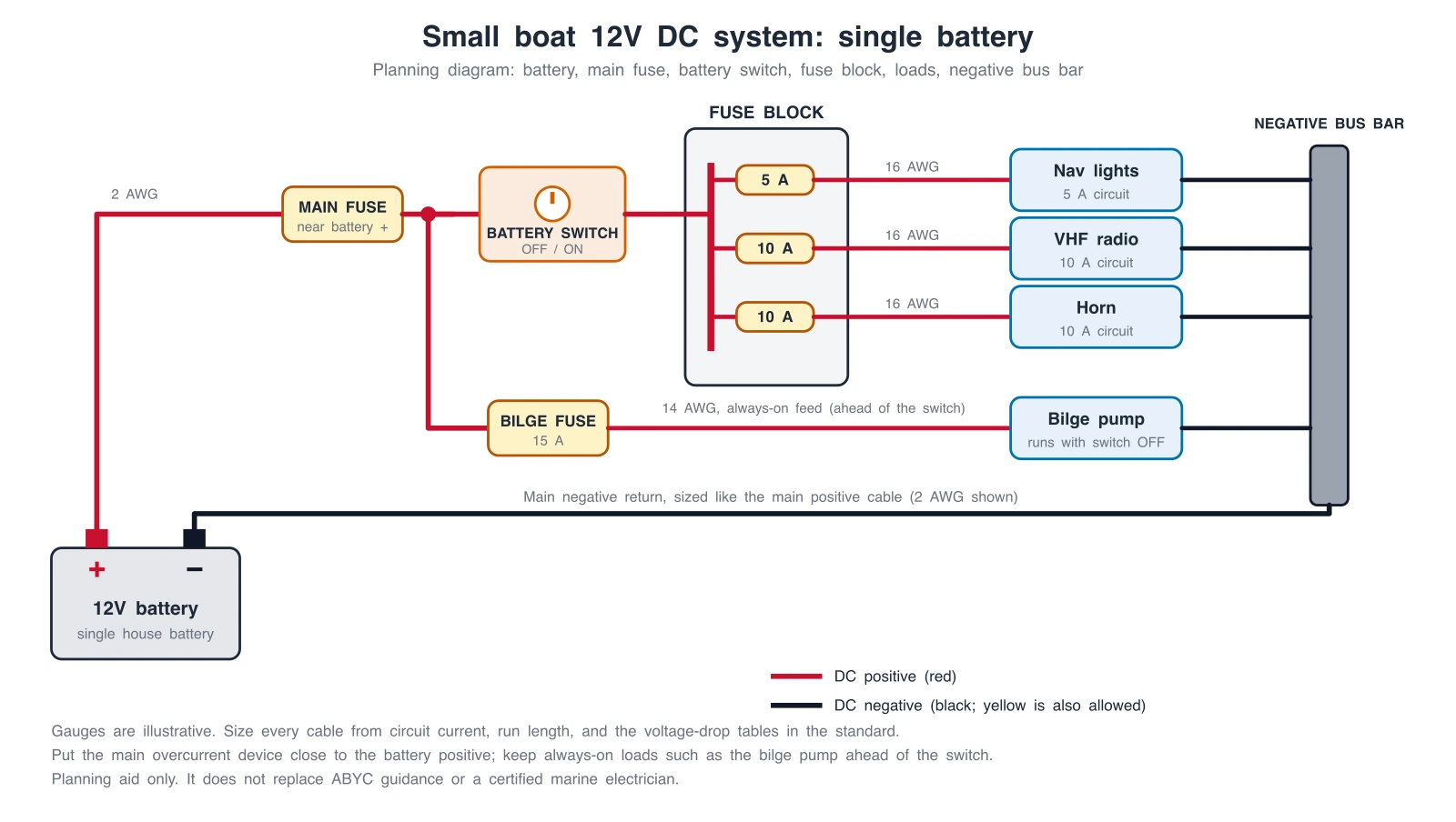
Boat Wiring Diagram Generator
Boat 12V systems: single and dual battery, battery switch, fuse block, bilge pump, and outboard.
 Physics
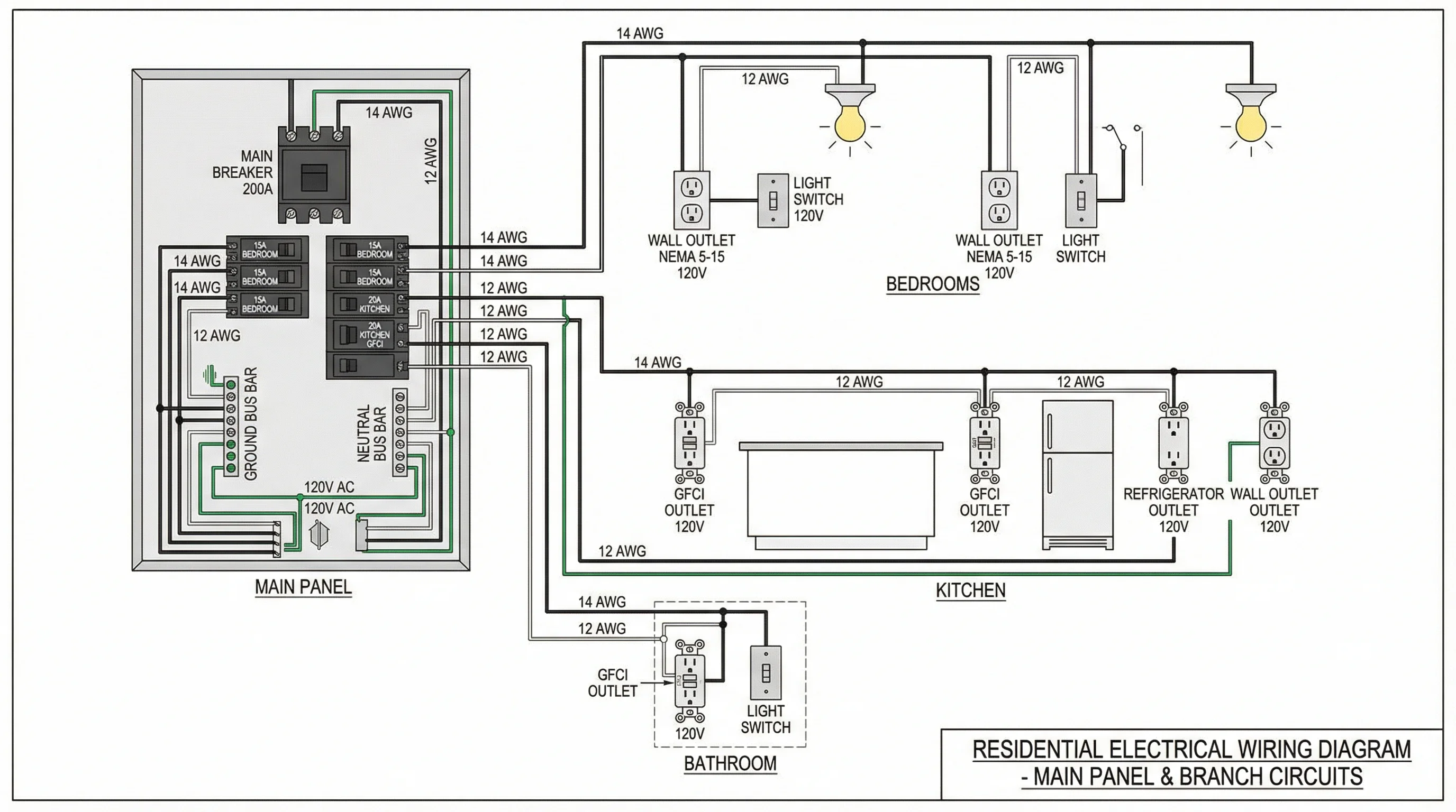
Wiring Diagram Maker
Wiring diagrams for home, automotive, appliance, and industrial systems from a plain-English description.
 Physics
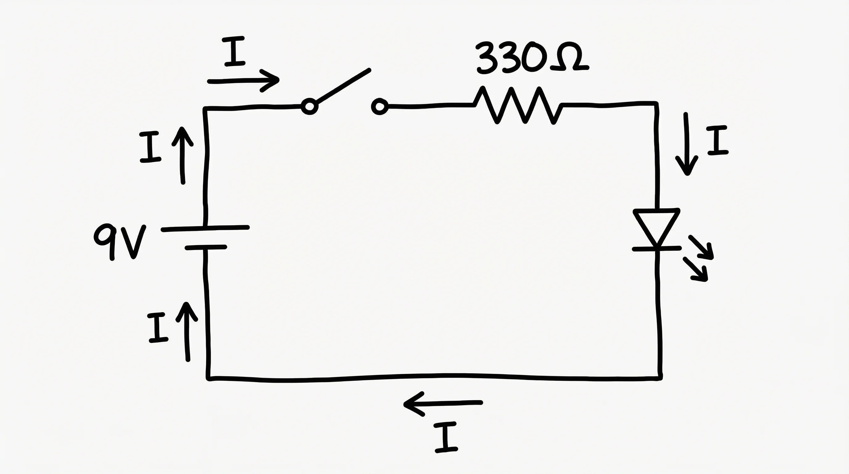
Circuit Diagram Maker
Draw circuit schematics with resistors, capacitors, batteries, and switches.
 Engineering
Single-Line Diagram Generator
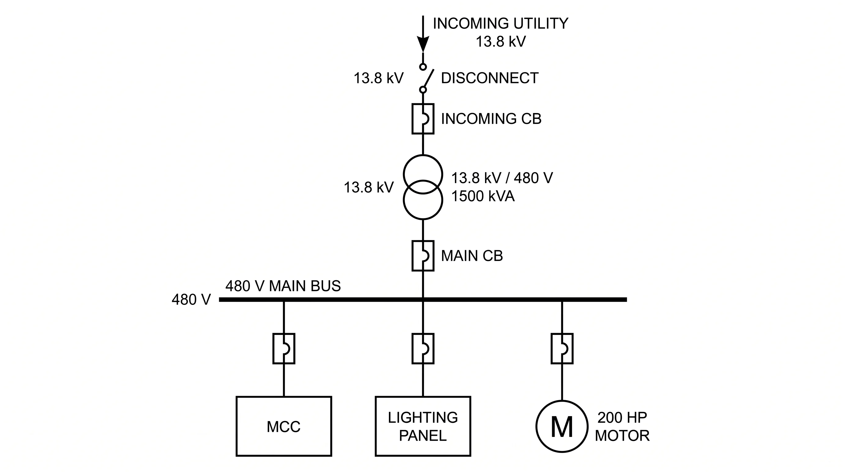
Facility-level one-line diagrams of sources, transformers, and feeders.