HVAC Diagram Generator for System & Cycle Figures
Make a custom HVAC system, refrigerant-cycle, or airflow diagram from a description. For class, bids, or service notes — not thermostat wiring.
AI HVAC Diagram Generator
Free preview on this page · Clean file download needs a
Used by 40,000+ teachers, students & researchers
Your HVAC diagram will appear here
Describe equipment, ducts, refrigerant or water loops — not thermostat terminals
HVAC Diagram Examples
System, refrigerant-cycle, airflow, and plant figures — not wiring
Residential Split System
A house-scale split system — outdoor unit, air handler, ducts, and vents — for a class or bid, not a pinout.
Heat-Pump Refrigerant Cycle
The four-component vapor-compression loop with high- and low-pressure sides marked.
Rooftop Unit + VAV
An RTU feeding three VAV zones — the figure a trainer or estimator actually needs.
Supply and Return Airflow
How air leaves the handler, reaches the rooms, and comes back — no wires.
Chiller Plant
Chiller, tower, pumps, and coils as a plant schematic for a lecture or service note.
Ductless Mini-Split
One outdoor unit, three indoor heads, and the refrigerant and drain lines between them.
What is an HVAC diagram?
An HVAC diagram is a mechanical picture of how a heating, ventilation, and air-conditioning system moves air, refrigerant, or water. It shows equipment (condenser, air handler, chiller, VAV box), the paths between them, and the labels a trainer, estimator, or service lead needs on a slide or a job note. It is not a thermostat pinout and it is not a ladder drawing of the 24-volt control circuit. This generator draws the system figure: units, ducts, refrigerant or water loops, and airflow — from a plain-English description.
HVAC system diagram vs HVAC wiring schematic
People search both phrases, but they want different pictures. A system or cycle diagram shows the mechanical plant: outdoor unit, indoor coil, ducts, VAV boxes, or the compressor–condenser–expansion–evaporator loop. An HVAC wiring schematic shows how the thermostat R, Y, G, and W terminals, transformer, contactor, and motors are electrically connected. If you need the electrical drawing, use the wiring diagram maker. Use this page when the job is “show how this building’s air or refrigerant moves,” not “which wire lands on which terminal.”
Diagram types this tool is built for
- Residential split and packaged systems: outdoor condenser, indoor air handler, ducts, vents, and filter.
- Refrigerant / heat-pump cycles: compressor, condenser, expansion device, evaporator, with high- and low-pressure sides marked.
- Commercial air side: rooftop units, VAV boxes, economizers, and zone airflow.
- Hydronic plants: chiller, cooling tower, pumps, and coil loops.
- Ductless and multi-split layouts: one outdoor unit and several indoor heads.
Who uses a custom HVAC figure
HVAC instructors need a clean cycle or plant drawing for tomorrow’s slide. Estimators and techs need a system sketch that matches the job in front of them — a three-zone VAV, a heat-pump swap, a mini-split add-on — not a stock house cutaway from image search. The figure is a teaching or communication draft: it should be labeled well enough to stand in front of, then checked against the actual equipment and code before anyone builds from it.
How to generate an HVAC diagram from a description
Name the equipment, the loops, and the job. “R-410A heat pump, show superheat and subcooling” is better than “HVAC diagram.” “RTU on the roof, three VAV zones, economizer” is better than “commercial HVAC.” Say whether you want a pictorial house cutaway, a refrigerant cycle, or a plant block schematic. Generate a few options, fix the labels that drifted, and download a PNG for the slide or the job folder. Do not ask this page for thermostat terminal letters — that drawing belongs on the wiring tool.
Accuracy and an honesty note
These are AI illustrations, not stamped mechanical drawings. The model can misplace a filter, swap supply and return, or invent a pipe that is not on the real unit. Use the output as a labeled draft for class, a bid conversation, or a service note, then check it against the manufacturer diagram and local code. For live electrical work, a licensed electrician or HVAC tech still owns the wiring.
Frequently Asked Questions
Related Engineering Tools
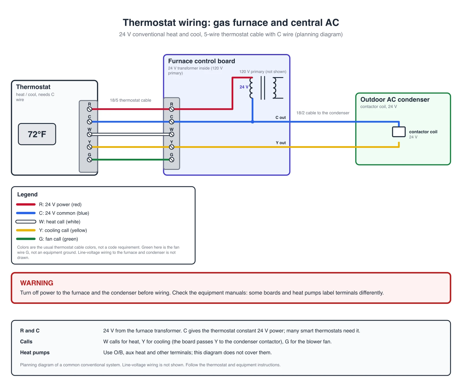 Engineering
Thermostat Wiring Diagram Generator
Exact thermostat wiring diagrams: heat-only, furnace with AC, and heat pump O/B.
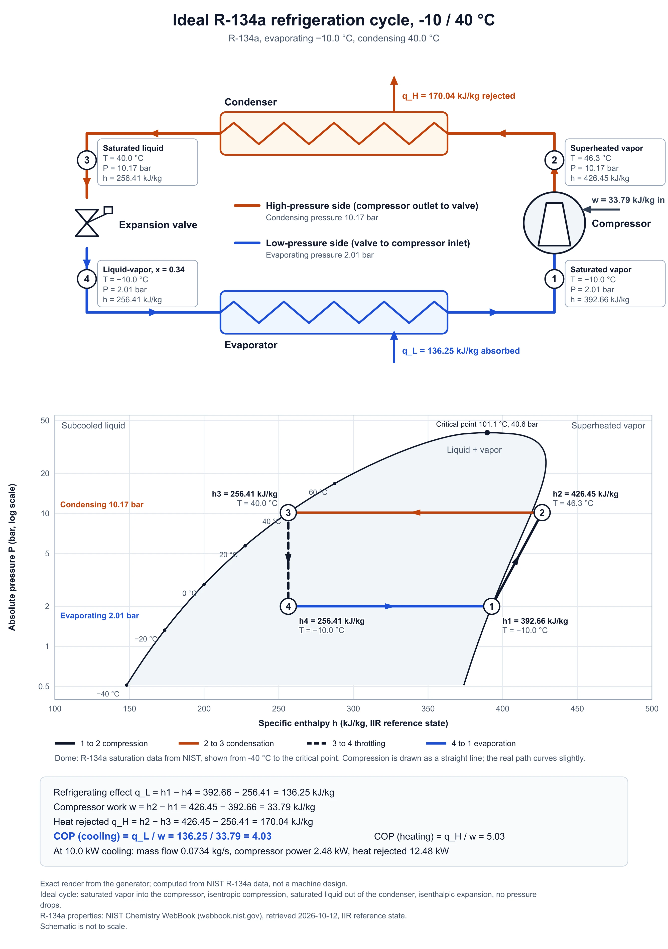 Engineering
Refrigeration Cycle Diagram Generator
The cycle itself: state points, an R-134a P-h diagram and COP, for when the figure is thermodynamics rather than a system layout.
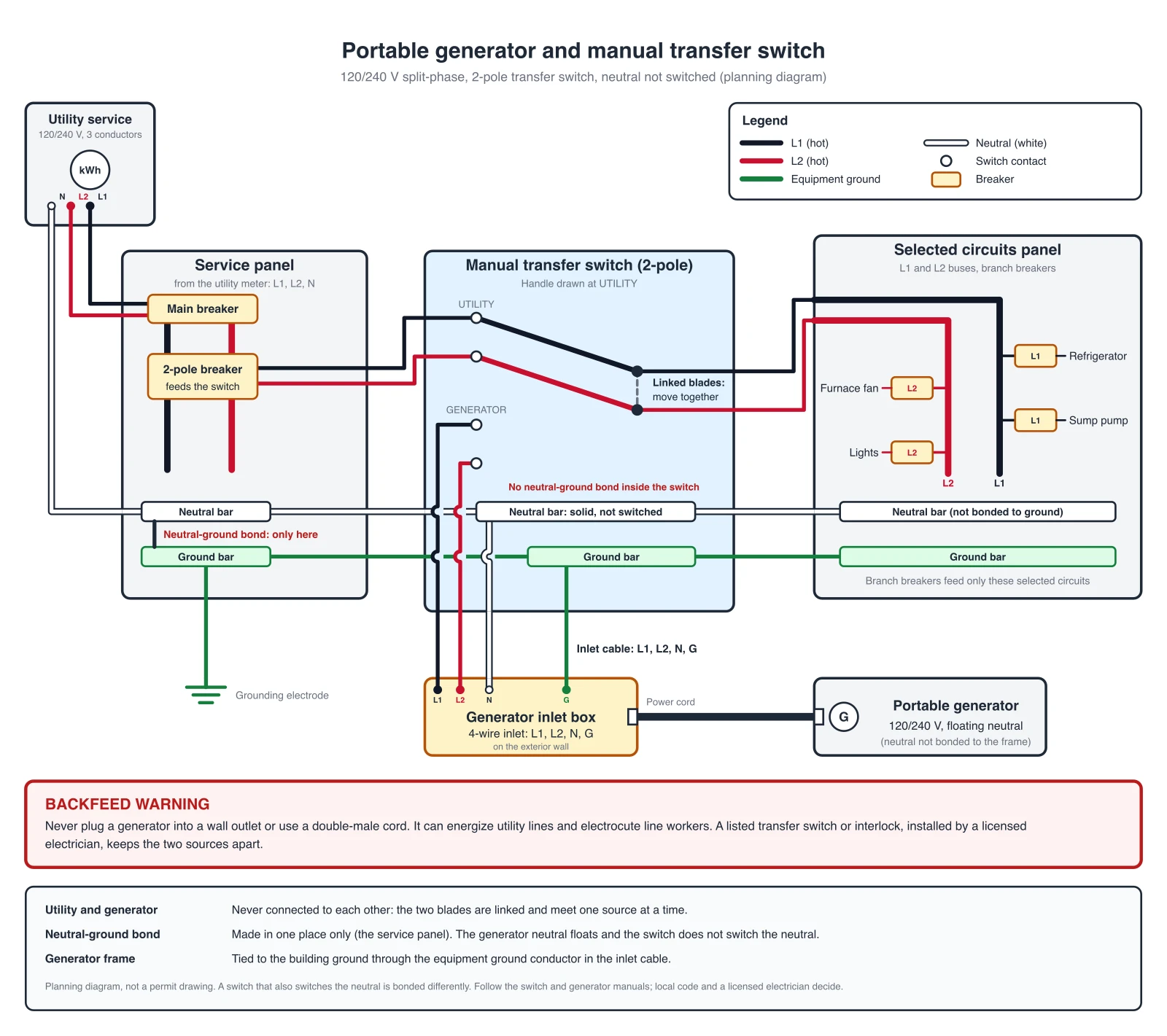 Engineering
Wiring Diagram Maker
Thermostat terminals, control wiring, and electrical connections — the drawing this page does not do.
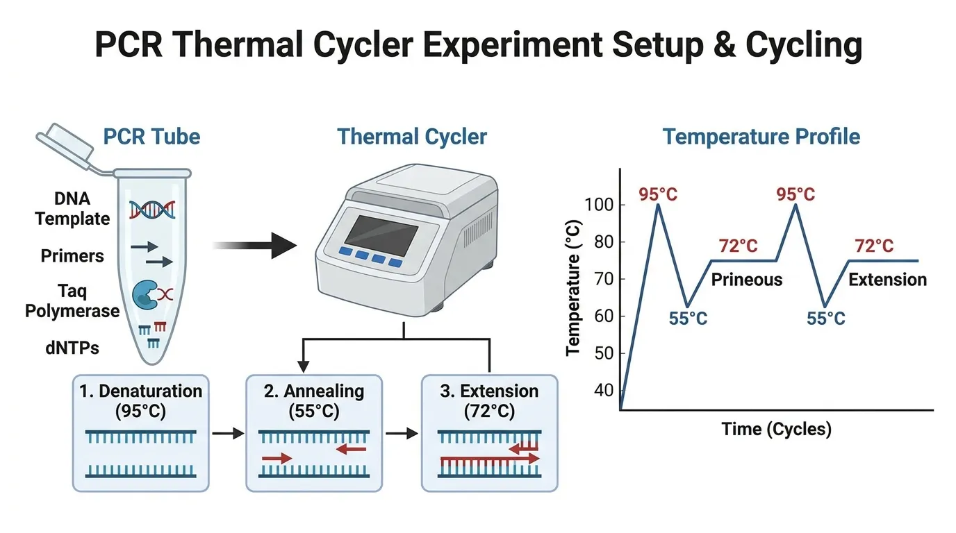 Engineering
Schematic Diagram Maker
Lab-apparatus and equipment schematics when the figure is a bench setup, not an HVAC plant.
 Engineering
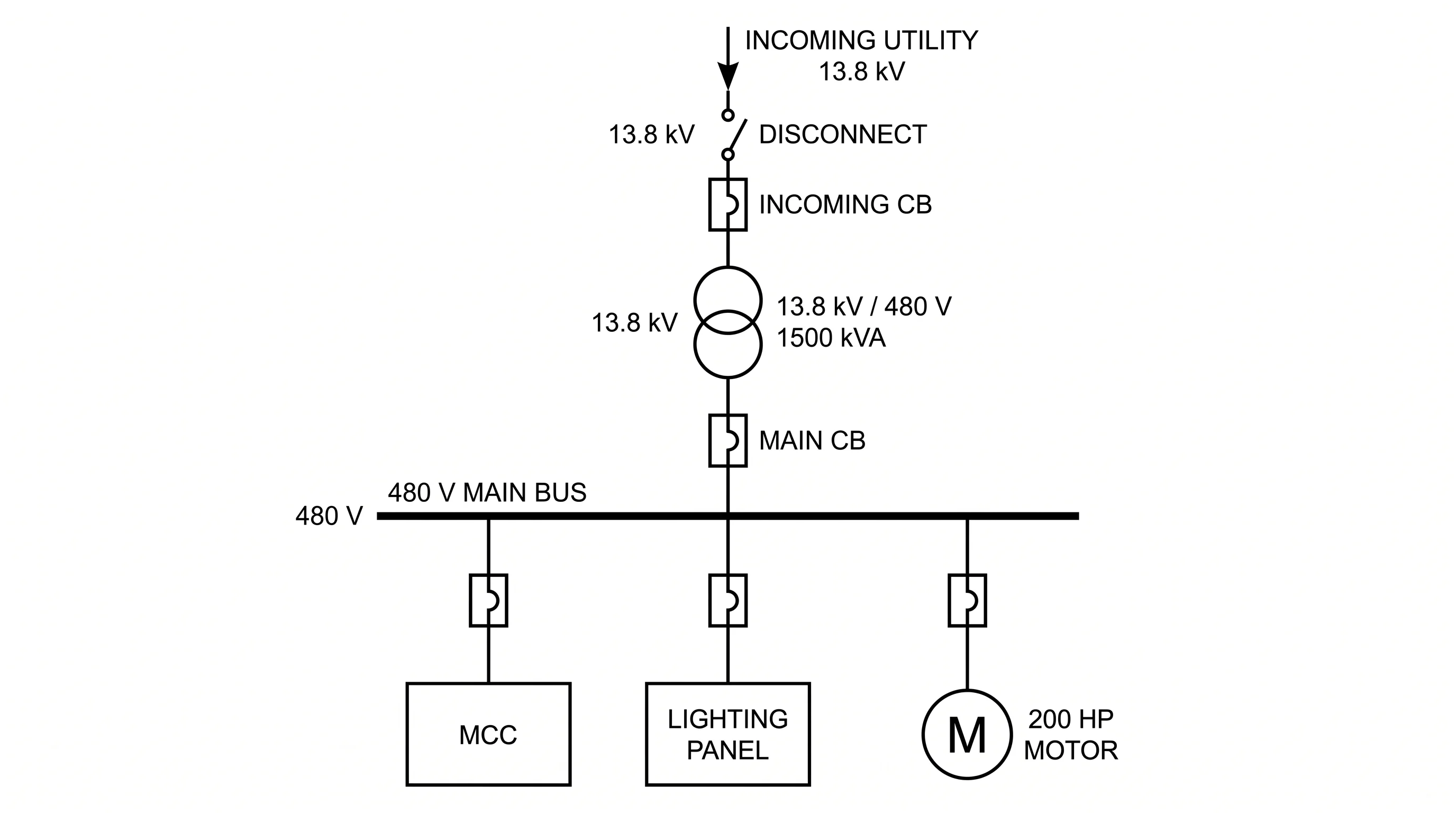
Single-Line Diagram Generator
Power-system one-line diagrams with transformers, buses, and breakers.