系统上下文图生成器 系统上下文图
描述您的系统,AI将自动生成展示系统边界、外部实体与数据流的专业上下文图。适用于系统分析、需求整理和利益相关方沟通。
系统上下文图生成器
免费试用 ·
上下文图将显示在此处
描述您的系统并点击生成
上下文图示例
浏览系统上下文图示例,或在上方生成您自己的图
电商系统上下文图
电商平台系统上下文图,展示中心系统与客户、支付网关、库存供应商和物流商等外部实体之间的订单、支付、物流跟踪与履约数据流。
医院管理系统上下文图
医院管理系统上下文图,外部实体包括患者、医生、保险公司、药房和检验科,通过预约、处方、理赔和检验结果等数据流相互连接。
银行系统上下文图
在线银行系统上下文图,展示核心银行平台与客户、ATM网络、中央银行、征信机构和商户系统等外部实体的交互关系。
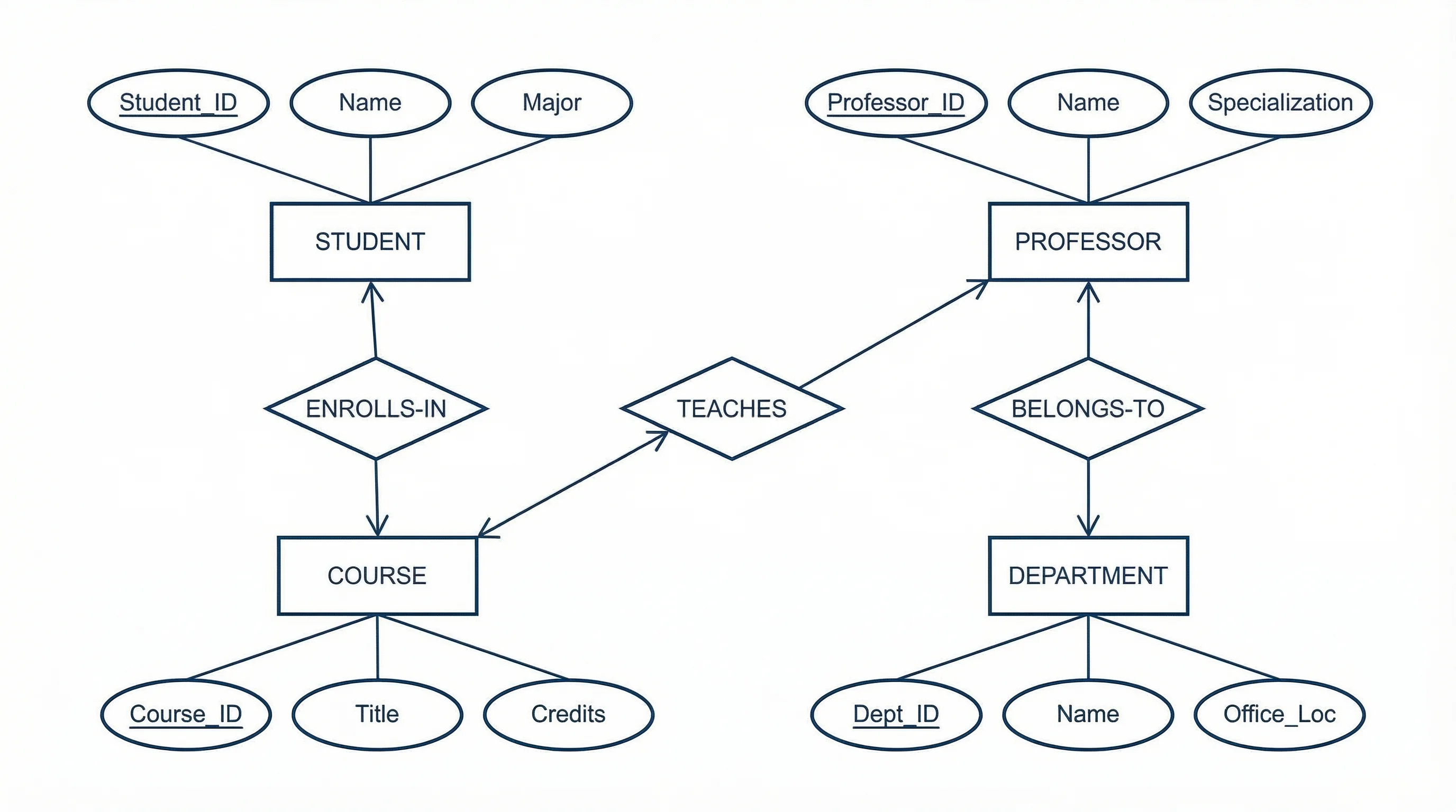
大学选课系统上下文图
大学选课系统上下文图,外部实体包括学生、指导教师、注册办、助学金办公室和院系负责人,通过选课、成绩和排课数据流相互连接。
供应链管理上下文图
供应链管理系统上下文图,展示中心系统与原材料供应商、制造商、配送仓库、零售商和物流合作伙伴等外部实体之间的数据流。
移动应用后端上下文图
移动应用后端系统上下文图,展示服务端系统与移动客户端、推送通知服务、数据分析平台、第三方API和应用商店等外部实体的交互关系。
什么是系统上下文图?
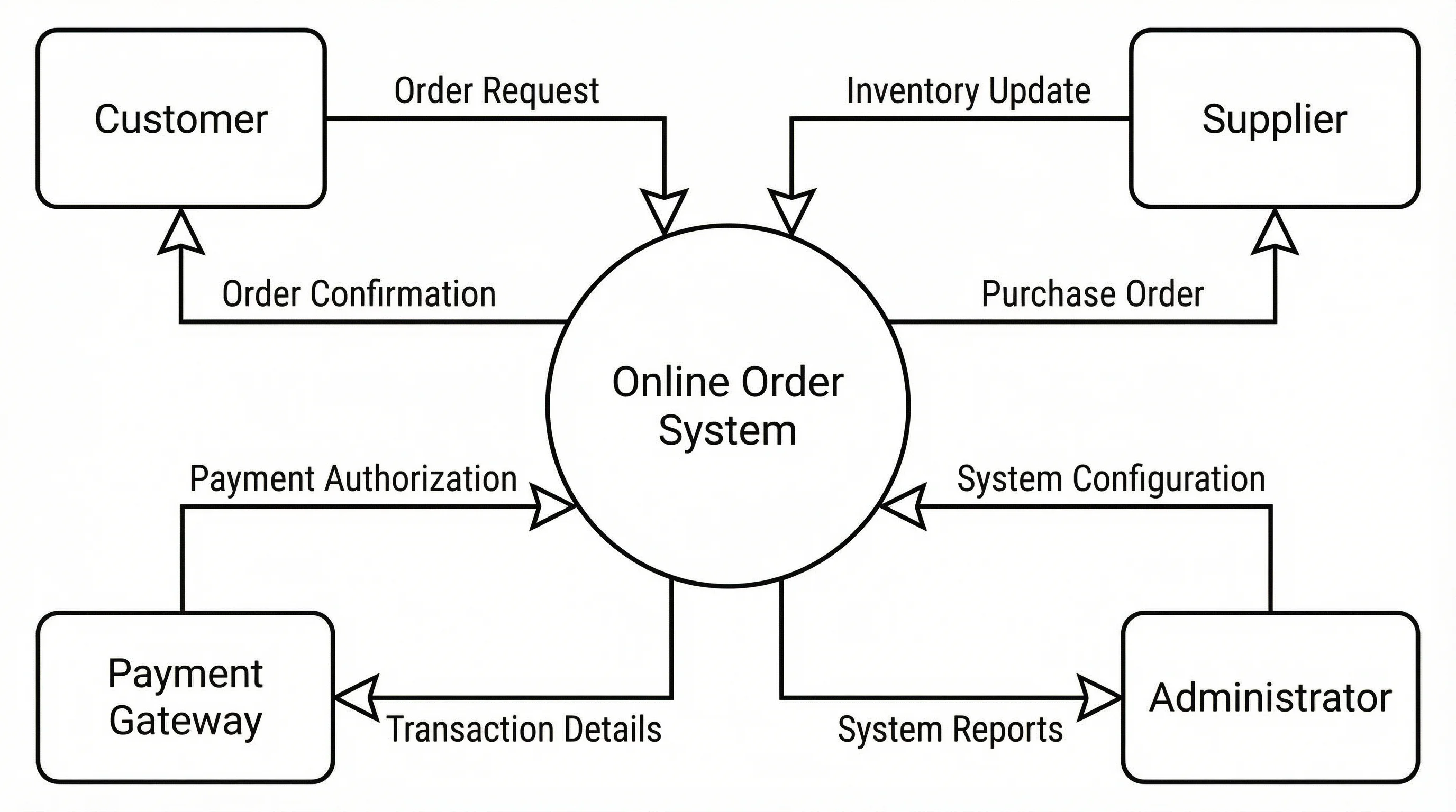
系统上下文图(也称为0级数据流图)是一种高层次的可视化图示,用于定义系统边界及其与外部实体的交互关系。它将整个系统以单一过程的形式置于图的中心,周围环绕着与之交互的人员、组织和其他系统。上下文图是结构化系统分析的起点,为利益相关方提供清晰的全局视图,呈现系统的功能范围和交互对象,而不涉及任何内部实现细节。
上下文图与数据流图的关系
- Level 0(上下文图):将整个系统表示为单一过程泡,显示外部实体及其数据流——即上下文图本身,提供最高层次的抽象视图
- Level 1 DFD:将上下文图中的单一过程分解为主要子过程,揭示内部数据存储和组件间的详细数据流
- Level 2+ DFD:进一步将Level 1的各子过程分解为更细粒度的子过程,在每个层级增加更多实现细节
- 上下文图确立了系统边界——中心过程内部的一切都是"系统",外部的一切代表外部参与者,是绘制详细DFD之前不可缺少的基础
如何创建系统上下文图
- 第一步——确定系统:将要建模的系统定义为单一过程(圆形或圆角矩形),置于图的中心并标注清晰的系统名称
- 第二步——识别外部实体:列出所有与系统交互的人员、组织和外部系统,以矩形形式分布在中心过程周围
- 第三步——定义数据流:在外部实体与中心过程之间绘制标注箭头,说明进出系统的信息流向——每条箭头应有描述性标签,如"订单请求"或"发票"
- 第四步——验证完整性:与利益相关方共同审查图示,确保所有外部交互均已记录,无遗漏的实体或数据流
- 第五步——精炼与文档化:优化布局提升可读性,确保符号一致,并为标注的数据流添加数据字典等支撑文档
何时使用系统上下文图
系统上下文图在项目初期最有价值,此时需要明确系统范围和边界。在需求收集阶段,它对于统一利益相关方对系统功能范围的认知至关重要。业务分析师使用上下文图与非技术利益相关方沟通,因为单一过程的视图避免了过多技术细节的干扰。它广泛应用于软件工程、系统工程和企业架构,用于记录系统接口。上下文图也是安全分析的基础,帮助团队识别数据进出系统的所有外部接触点。