
Use Case Diagram Generator Guide: Create UML Use Cases from Text
Learn how to use a use case diagram generator, define actors and system boundaries, write better prompts, and avoid common UML notation mistakes.
A use case diagram generator helps turn a feature description into a structured UML diagram with actors, use cases, a system boundary, and relationships such as include or extend. That is useful when you need a quick requirements diagram for a product spec, software design document, classroom assignment, or stakeholder presentation.
The hard part is not drawing ovals and stick figures. The hard part is deciding what belongs in the diagram. This guide explains how to prepare a use case diagram, what to enter into a generator, how to read the output, and how to fix the mistakes that make use case diagrams confusing.

Use Case Diagram Generator
Create UML use case diagrams from actors, system boundaries, use cases, and include or extend relationships.
Generate a use case diagram ->Quick Answer: How Do You Use a Use Case Diagram Generator?
To use a use case diagram generator:
- Name the system you are modeling.
- List the external actors, such as
Customer,Admin,Payment Gateway, orInventory System. - List the goals each actor wants to accomplish.
- Keep each use case as a verb phrase, such as
Place OrderorReset Password. - Add a system boundary so readers know what is inside the software.
- Use
includefor required reusable behavior. - Use
extendfor optional or conditional behavior. - Review the generated diagram and remove implementation details that belong in sequence, activity, or class diagrams.
A good prompt is more important than a long prompt. The generator needs actors, goals, relationships, and scope. It does not need database tables, UI button names, or every step of a workflow.
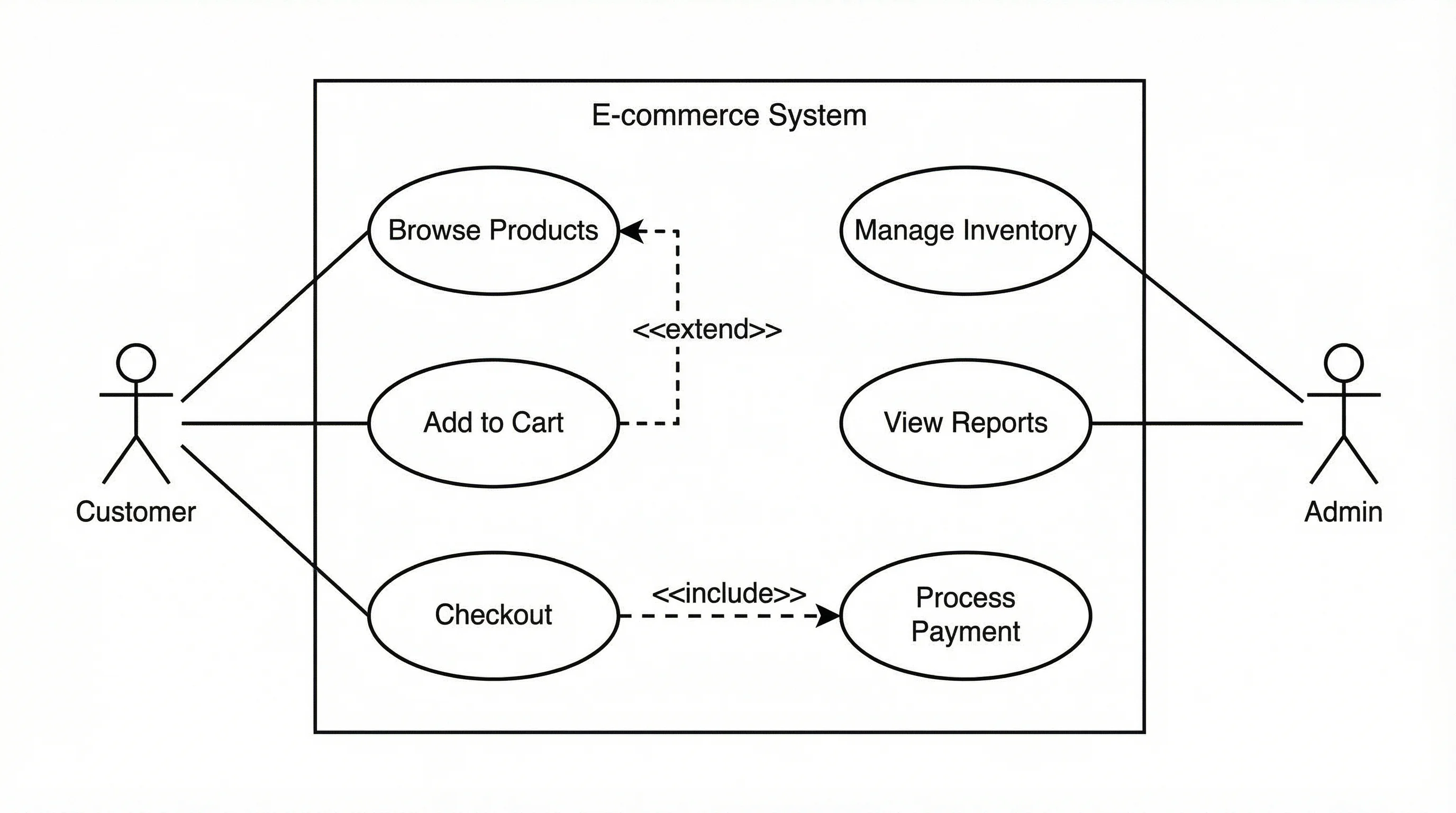
A use case diagram should show external actors and their goals inside a clearly named system boundary.
What a Use Case Diagram Shows
A use case diagram is a UML diagram that shows what external users or systems can do with a system. It is usually used early in requirements analysis, before detailed design.
The core elements are simple:
| Element | Meaning | Example |
|---|---|---|
| Actor | External person, role, or system | Customer, Admin, Payment Gateway |
| Use case | Goal the actor wants to accomplish | Place Order, View Report, Cancel Booking |
| System boundary | Scope of the system being modeled | Online Store System |
| Association | Actor participates in a use case | Customer -> Place Order |
| Include | Required reused behavior | Checkout includes Process Payment |
| Extend | Optional or conditional behavior | Apply Coupon extends Checkout |
| Generalization | Specialized actor or use case | Premium Customer is a type of Customer |
Lucidchart's use case diagram guide describes use case diagrams as a way to visualize how users interact with a system. Visual Paradigm's guide emphasizes the same point from a requirements perspective: the diagram captures system behavior from the user's point of view.
That user-centered focus is why use case diagrams are useful. They do not try to show every internal class, database operation, screen transition, or API call. They show what the system must let actors accomplish.
When a Use Case Diagram Is the Right Diagram
Use a use case diagram when the question is:
- Who interacts with this system?
- What goals do they have?
- What is inside the system scope?
- What external systems participate?
- Which behaviors are required, optional, or shared?
Do not use a use case diagram when the question is:
- What order do steps happen in?
- Which classes call each other?
- What database tables are needed?
- How does the UI transition between screens?
- What happens inside one use case?
Use this decision table:
| Need | Better diagram |
|---|---|
| Show user goals and system scope | Use case diagram |
| Show step-by-step workflow | Activity diagram |
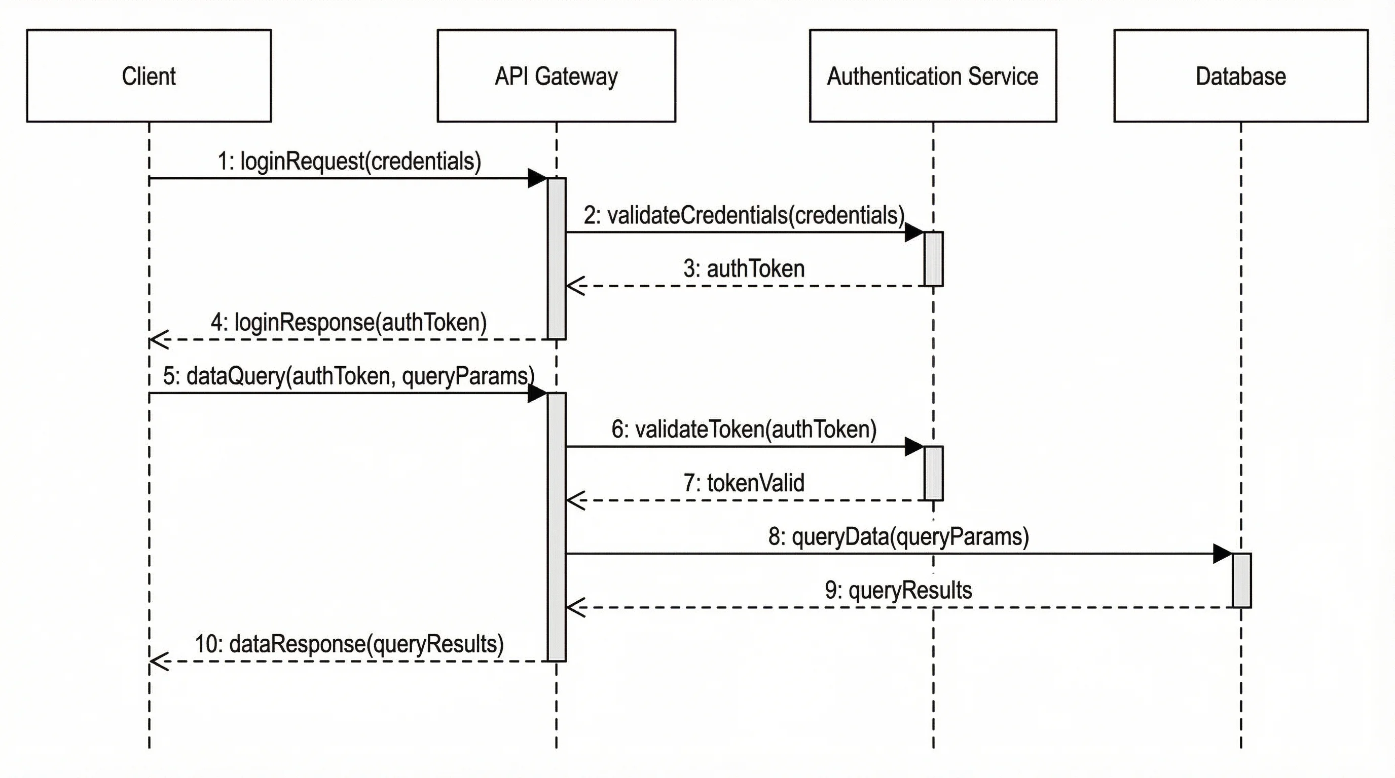
| Show messages between objects or services | Sequence diagram |
| Show classes, attributes, and methods | Class diagram |
| Show database entities and relationships | ER diagram |
| Show states of one object over time | State diagram |
For the broader map of UML types, see our UML diagram types guide.
Step 1: Define the System Boundary
The system boundary is the rectangle that contains the use cases. It answers the question: "What system are we talking about?"
Good system boundary names:
Online Banking SystemLibrary Management SystemFood Delivery AppCourse Registration PortalHospital Appointment System
Weak system boundary names:
SoftwarePlatformProjectUser InterfaceDatabase
A boundary that is too broad makes the diagram vague. A boundary that is too narrow forces you to draw internal implementation details as if they were external behavior.
Example:
| Poor boundary | Better boundary |
|---|---|
Ecommerce | Online Store Checkout System |
School App | Student Course Registration Portal |
Healthcare | Patient Appointment Booking System |
When using a generator, put the boundary in the first sentence of your prompt:
Create a UML use case diagram for an Online Store Checkout System.That one sentence gives the generator a scope anchor.
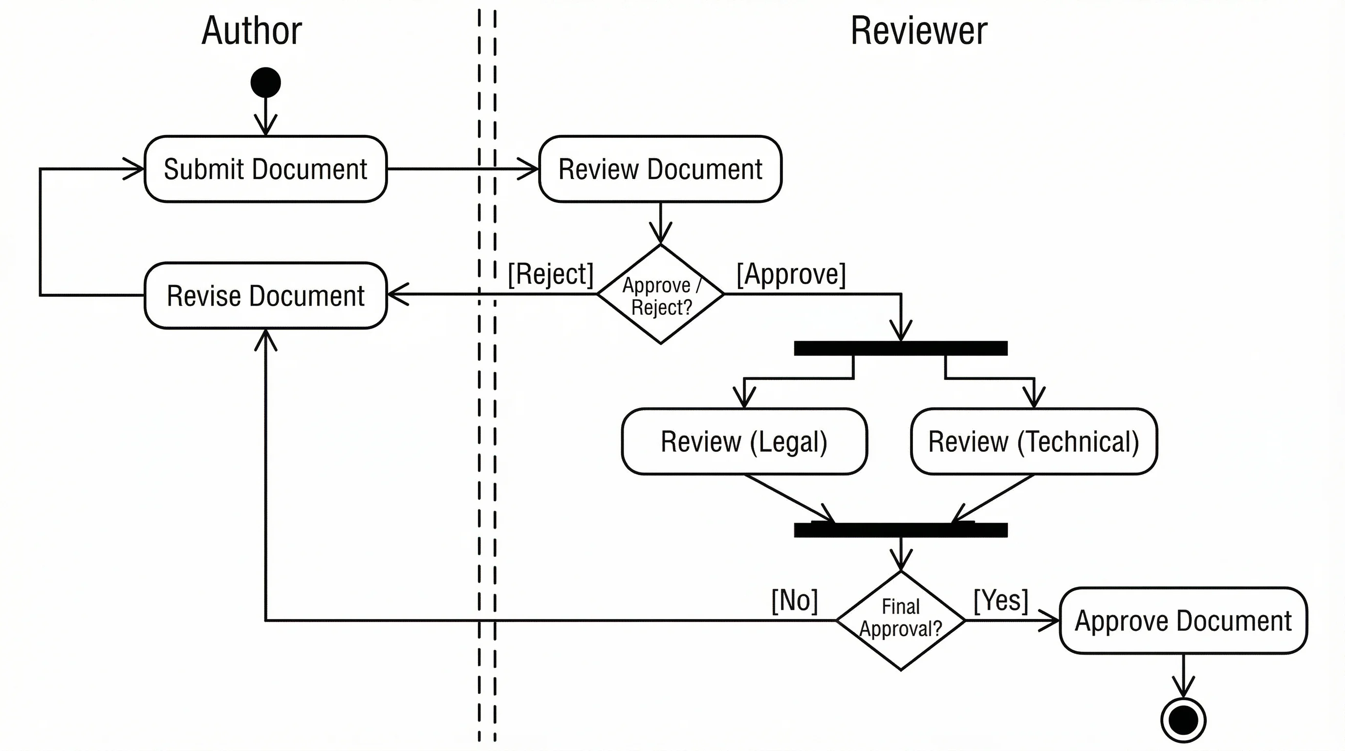
If you need to show steps inside a use case, switch to an activity diagram instead of overcrowding the use case diagram.
Step 2: Identify Actors
An actor is outside the system. It can be a human role, another software system, a device, or an organization.
Common actor types:
| Actor type | Example |
|---|---|
| Human role | Customer, Librarian, Instructor, Admin |
| External system | Payment Gateway, Email Service, Inventory System |
| Organization | Insurance Provider, Shipping Carrier |
| Device | Barcode Scanner, Smart Sensor |
| Time or scheduler | Billing Scheduler, Backup Job |
Avoid naming actors after individual people. Use roles instead.
| Too specific | Better |
|---|---|
| Alice | Customer |
| Mr. Smith | Instructor |
| Finance team member John | Accountant |
UML-diagrams.org's use case actor reference is helpful here because it treats actors as external roles that interact with the subject, not as internal components.
A common mistake is making the system itself an actor. For example, in a banking system, Banking App is usually the system boundary, not an actor. Customer, Bank Admin, and Payment Network are actors.
Step 3: Write Use Cases as Goals
A use case should be a goal the actor wants to accomplish. Use verb phrases.
Good use case names:
Register AccountLog InSearch ProductsPlace OrderTrack ShipmentGenerate Monthly ReportCancel Reservation
Weak use case names:
ButtonDatabaseOrder tableAPI callForm validationPayment screen
Those weak examples may matter in implementation, but they are not user goals.
Before using a generator, make a compact actor-goal table:
| Actor | Goal / use case |
|---|---|
| Customer | Register Account |
| Customer | Search Products |
| Customer | Place Order |
| Customer | Track Shipment |
| Admin | Manage Inventory |
| Admin | Process Refund |
| Payment Gateway | Authorize Payment |
This table is often enough to generate a usable first draft.
Step 4: Use Include and Extend Correctly
Many generated use case diagrams become messy because include and extend are used as decoration. They have specific meanings.
Include
Use include when one use case always reuses another required behavior.
Example:
Place Order includes Process Payment.If every order must process payment, Process Payment is required reusable behavior.
Extend
Use extend when behavior is optional, conditional, or triggered only in some cases.
Example:
Apply Coupon extends Checkout.Not every checkout uses a coupon, so this behavior is optional.
Sparx Systems' UML use case relationship reference gives a concise overview of associations, include, extend, and generalization in use case diagrams.
Use this quick check:
| Relationship | Ask this question |
|---|---|
| Include | Does the base use case always need this behavior? |
| Extend | Does this behavior happen only sometimes? |
| Generalization | Is this actor or use case a specialized version of another? |
| Association | Does this actor participate in this use case? |
If you are unsure, use a simple association first. A readable diagram with fewer relationship types is usually better than a dense diagram with questionable notation.
Step 5: Write a Better Prompt for a Generator
A weak prompt:
Make a use case diagram for ecommerce.A better prompt:
Create a UML use case diagram for an Online Store Checkout System.
Actors: Customer, Guest Customer, Registered Customer, Admin, Payment Gateway, Shipping Carrier.
Use cases: Browse Products, Add Item to Cart, Checkout, Process Payment, Apply Coupon, Track Shipment, Manage Inventory, Process Refund.
Relationships: Checkout includes Process Payment. Apply Coupon extends Checkout. Registered Customer specializes Customer. Payment Gateway participates in Process Payment. Shipping Carrier participates in Track Shipment.
Show the system boundary and keep the diagram readable.
This prompt works because it gives:
- System scope
- Actors
- Use cases
- Relationship rules
- Readability preference
For AI tools, specificity beats length. If the first result is cluttered, ask for fewer use cases, simpler relationships, or one actor group at a time.
Example 1: Online Store Use Case Diagram
For an online store, a clean first version might include:
| Actor | Use cases |
|---|---|
| Guest Customer | Browse Products, Register Account |
| Registered Customer | Add Item to Cart, Checkout, Track Order |
| Admin | Manage Products, Process Refunds |
| Payment Gateway | Authorize Payment |
| Shipping Carrier | Update Delivery Status |
Good relationship choices:
CheckoutincludesAuthorize Payment.Apply CouponextendsCheckout.Registered CustomerspecializesCustomer.Shipping Carrieris associated withUpdate Delivery Status.
Do not add every UI step. Click Add to Cart Button, Open Modal, and Validate Text Field belong in workflow or UI documentation, not in the use case diagram.
Example 2: Library Management System
A library management system might include:
| Actor | Use cases |
|---|---|
| Member | Search Catalog, Borrow Book, Renew Loan, Reserve Book |
| Librarian | Add Book, Update Book Record, Manage Member Account |
| Payment System | Collect Fine |
| Notification Service | Send Due Date Reminder |
Prompt:
Create a UML use case diagram for a Library Management System.
Actors: Member, Librarian, Payment System, Notification Service.
Use cases: Search Catalog, Borrow Book, Renew Loan, Reserve Book, Add Book, Update Book Record, Manage Member Account, Collect Fine, Send Due Date Reminder.
Relationships: Borrow Book includes Check Availability. Renew Loan extends Borrow Book when the book is not reserved. Payment System participates in Collect Fine. Notification Service participates in Send Due Date Reminder.
This is enough for a generator to produce a diagram that stakeholders can review.
When the reviewer asks what happens after a user selects a use case, create a sequence diagram or activity diagram for that individual scenario.
Common Mistakes in Generated Use Case Diagrams
Adding internal components as actors
Database, Controller, and Login Form are usually internal parts of the system. They should not be actors unless they are genuinely outside the system boundary.
Making use cases too small
Click Submit, Enter Email, and Display Error are UI steps. A use case should be closer to Reset Password.
Making use cases too large
Manage Business is too broad. Break it into concrete user goals such as Manage Inventory, Approve Refund, and Generate Sales Report.
Overusing include and extend
Too many dashed arrows make the diagram harder to read. Use simple associations unless the relationship adds real meaning.
Forgetting the system boundary
Without a boundary, readers cannot tell what belongs to the system and what is external.
Mixing requirements and implementation
A use case diagram should not show classes, database tables, API endpoints, or deployment nodes. Use other diagrams for those.
How to Review a Generated Diagram
After generating the diagram, use this checklist:
| Check | Question |
|---|---|
| Scope | Is the system boundary named clearly? |
| Actors | Are all actors outside the system? |
| Goals | Are use cases named as user goals? |
| Relationships | Are include and extend used only where they add meaning? |
| Readability | Can a stakeholder understand it in 30 seconds? |
| Completeness | Are important external systems included? |
| Separation | Are implementation details kept out? |
If a diagram fails the readability check, reduce it. Create one high-level diagram and separate detailed diagrams for complex scenarios.
Use Case Diagram vs User Story Map
Use case diagrams and user stories are related, but they serve different purposes.
| Format | Best for |
|---|---|
| Use case diagram | Showing actors, goals, and system scope visually |
| User story | Describing a feature from a user's perspective |
| User story map | Organizing product work by workflow and priority |
| Acceptance criteria | Defining testable completion conditions |
A use case diagram can help you discover user stories. For example:
As a registered customer, I want to track my shipment so that I know when my order will arrive.That story maps naturally to the actor Registered Customer and the use case Track Shipment.
When to Use PlantUML, Mermaid, or a Visual Generator
Different tools fit different workflows:
| Tool style | Best for | Tradeoff |
|---|---|---|
| AI generator | Fast first draft from requirements text | Needs human review |
| Visual editor | Precise manual layout and stakeholder presentation | Slower to start |
| PlantUML | Version-controlled UML in docs | Requires syntax |
| Mermaid | Lightweight diagrams in Markdown | Use case support is less central than flowcharts/sequence |
| Draw.io / diagrams.net | Free general-purpose diagramming | Manual structure |
PlantUML's use case diagram docs are useful if your team keeps diagrams in Git. Diagrams.net is useful when you want a free visual editor. A generator is most useful when you have plain-language requirements and need a structured first draft quickly.
How to Use the Diagram in a Product Spec
For a product requirements document or system design document, include:
- The diagram.
- A one-sentence system scope.
- A short actor list.
- One table mapping actors to use cases.
- Notes for any include or extend relationship that may be controversial.
- Links to detailed activity or sequence diagrams for complex flows.
Example caption:
Use case diagram for the Online Store Checkout System. Customers can add items, checkout, apply coupons, and track orders. The Payment Gateway and Shipping Carrier are external systems that participate in payment authorization and delivery updates.For technical workflows, pair the use case diagram with our activity diagram generator, sequence diagram generator, or software architecture diagram generator.
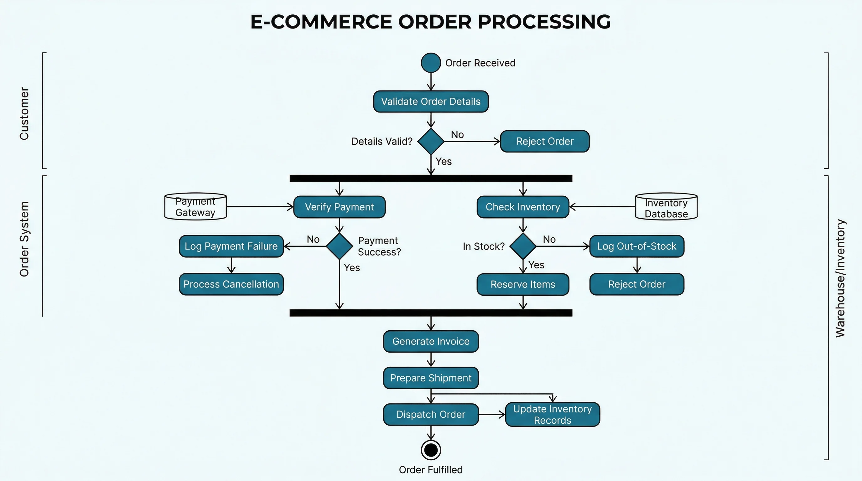
Activity Diagram Generator
Turn a workflow description into a clear UML activity diagram for steps, decisions, and parallel branches.
Sequence Diagram Generator
Show messages between users, services, APIs, and databases for one specific use case scenario.
Frequently Asked Questions
What is a use case diagram generator?
A use case diagram generator is a tool that creates a UML use case diagram from structured input or a text description. It usually identifies actors, use cases, system boundaries, and relationships such as include, extend, and generalization.
What should I include in a use case diagram prompt?
Include the system name, actors, actor goals, and any known relationships. A strong prompt says what system is being modeled, lists external actors, names use cases as verb phrases, and specifies required include or optional extend relationships.
What is an actor in a use case diagram?
An actor is an external role, person, organization, device, or system that interacts with the system boundary. Examples include Customer, Admin, Payment Gateway, Notification Service, and Shipping Carrier.
What is the difference between include and extend?
Use include when one use case always reuses required behavior from another use case. Use extend when behavior is optional or conditional. For example, Checkout may include Process Payment, while Apply Coupon may extend Checkout.
Should database tables appear in a use case diagram?
Usually no. Database tables, controllers, UI components, and API endpoints are internal implementation details. A use case diagram should focus on external actors and the goals they accomplish through the system.
Can a use case diagram replace user stories?
No. A use case diagram gives a visual overview of actors and goals, while user stories describe individual features from a user's perspective. They work well together: the diagram helps discover stories, and stories add detail.
Is a use case diagram the same as a flowchart?
No. A use case diagram shows who interacts with the system and what goals they have. A flowchart or activity diagram shows the step-by-step process inside one workflow or use case.
How detailed should a use case diagram be?
A use case diagram should be detailed enough to show important actors and goals, but simple enough for a stakeholder to understand quickly. If one diagram becomes crowded, split it into a high-level overview and separate diagrams for major subsystems.
Conclusion
A use case diagram generator can save time, but it still needs good input. Start with system scope, actors, and user goals. Add include only for required reused behavior and extend only for optional behavior. Keep implementation details out of the diagram.
The best generated diagrams are not the most complex ones. They are the diagrams that help a stakeholder answer three questions quickly: who uses this system, what can they do with it, and what is inside the system boundary?
分类
更多文章

Central Dogma Diagram Guide: DNA to RNA to Protein
Learn how to read and draw a central dogma diagram, including DNA, mRNA, transcription, translation, ribosomes, codons, and common mistakes.
")
15 Illustration and Infographic Design Styles Explained (2026)
Explore 15 illustration and infographic design styles with examples: flat, isometric, 3D, hand-drawn, minimalist, vector, cartoon, line art and more.

Definition of Terms in Research: Thesis Examples, Format & Chapter 1 Guide
What definition of terms means in research and thesis Chapter 1, with examples, format rules, alphabetical order guidance, and common mistakes.