RAG & LLM App Architecture Diagram Generator for AI Agents
Generate a RAG architecture diagram or AI agent architecture diagram from a text prompt, with exact reference pipelines for retrieval, memory, and tools.
Create Your LLM Architecture Diagram
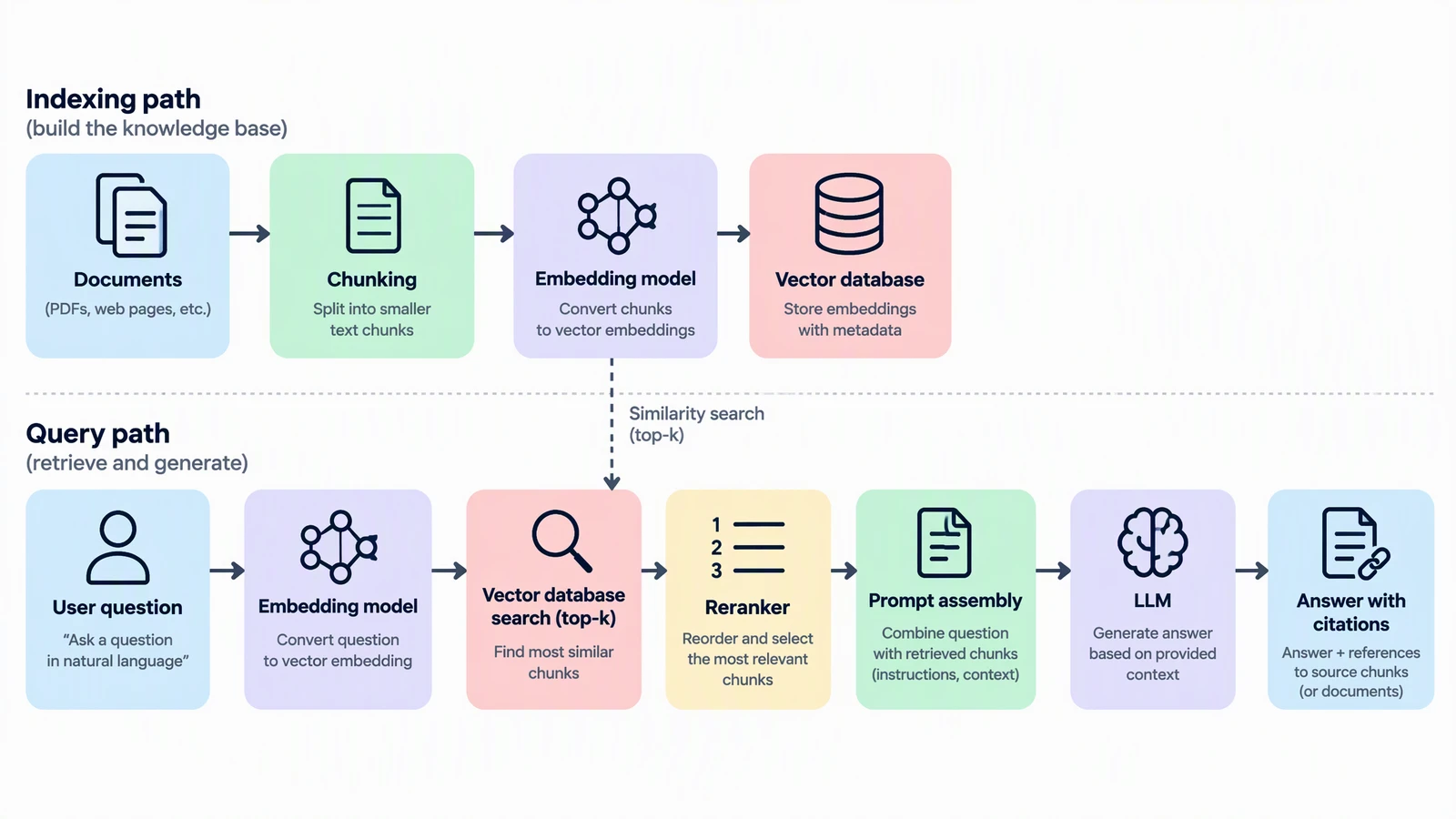 Example: RAG indexing and query pathsView full size
Preview is free on this page ·
Your architecture diagram will appear here
AI diagrams are drafts. Check every arrow direction and label before use.
LLM App Architecture Diagram Examples
Two exact reference diagrams drawn in code, plus three AI diagrams with their known flaws noted. AI diagrams need human review.
Standard RAG pipeline (exact diagram)
Drawn in code, not by AI: indexing path (documents, chunking, embedding, vector store) and query path (rewrite, embed, retrieve, rerank, assemble prompt, generate, cite). The dashed link marks the shared embedding model. Component categories, not product picks.
Single-agent loop (exact diagram)
Drawn in code: the plan, tool call, observation loop with a step limit, memory read and write, a tool catalog, and guardrails on the way in and out.
RAG indexing and query paths (AI diagram)
AI-generated from a text prompt. The component names and the left-to-right order are right, but the wiring is not. Known flaws: the dashed similarity-search arrow ends at a query-side box and starts at the indexing-side embedding box, so the vector database is never connected to retrieval, and no arrow returns the retrieved text chunks.
AI agent architecture (AI diagram)
AI-generated from a text prompt. Known flaws: the top and bottom halves are two separate views that are not connected to each other; the loop goes from Observation straight to Final answer, never back to the planner or through the output guardrails; and the guardrails sit beside the LLM instead of on the main flow. Use the exact diagram for the loop.
Agentic RAG (AI diagram)
AI-generated from a text prompt. Known flaws: the "Retrieve again if evidence is weak" arrow points from the tool to the agent, the wrong way, and duplicates the return path; "answer directly" also leads to a grounded answer with citations, although nothing was retrieved to cite; and the arrows to the two data stores are one-way, so returned passages are implied.
What an LLM application architecture diagram shows
An LLM application architecture diagram maps the parts around a language model and the direction data moves between them. Two designs account for most of the diagrams people search for: retrieval-augmented generation (RAG), where the model answers from documents it retrieves at question time, and AI agents, where the model plans, calls tools, reads the results, and repeats. This page covers both. Describe your system in the prompt box, generate a draft, and compare it with the exact reference diagrams in the gallery below.
RAG architecture: the components and the order they run in
- Documents and chunking: source files are split into passages, ideally one idea each, with metadata such as title and source ID.
- Embedding model: turns each chunk into a vector. The same embedding model must embed the query, or the vectors will not be comparable.
- Vector store: holds the vectors with the chunk text and source IDs, and answers similarity searches.
- Query embedding and retrieval: the question is embedded with the same model, the store is searched with that vector, and the top-k chunks come back, optionally with metadata filters or a keyword index alongside.
- Reranker: re-scores the retrieved chunks against the question and keeps the best top-n.
- Prompt assembly and generation: instructions, the question, and the chunks go to the LLM, which answers from that context.
- Citations: source IDs stored with each chunk let the answer point back to where each claim came from.
Two paths, not one line
The most common mistake in a RAG diagram is drawing one straight line from documents to answer. Indexing runs offline whenever documents change; the query path runs on every question. They meet in two places: the vector store, which indexing writes and retrieval reads, and the embedding model, which both paths share. Drawing the two lanes separately makes it clear where to cache, where to monitor, and which part to rebuild when your documents change.
AI agent architecture: the loop around the model
- Planner (LLM): reads the goal and the context, breaks the goal into steps, and chooses the next action.
- Tools: the actions the agent is allowed to take, such as search, code execution, API calls, and database queries.
- Observation: the tool result, including errors, is added to the context before the next planning step.
- Memory: short-term context for the current task, and a long-term store for facts and preferences that persist across tasks.
- Guardrails: input checks before the planner, output checks before the user, and permission, argument, and step-limit checks around tool calls.
- Stopping rule: the loop ends when the goal is met or a step limit is reached. A diagram without an exit is missing the most important arrow.
How RAG and agents connect
A fixed RAG pipeline always runs the same steps in the same order. In agentic RAG, retrieval becomes one tool in the agent loop: the agent decides whether to search, which source to query, and whether to search again when the evidence is weak. When you draw this, keep the retrieval box and the vector store from the RAG diagram, and move them behind the tool call in the agent diagram. The prompt examples above include an agentic RAG version.
How to generate an LLM architecture diagram from text
- Name the components you actually use, in plain categories: embedding model, vector store, reranker, planner, memory, tools.
- State the flow in order and say which arrows are data flow and which are optional.
- Ask for a white background, no brand logos, and legible English labels.
- Generate, then check every arrow direction and every box name against your design. Re-prompt to fix anything that is wrong.
Exact diagrams vs AI illustration on this page
The two exact diagrams are drawn in code, so every box, arrow, and label is placed on purpose. The three AI diagrams were generated from the prompts shown, and each caption lists the flaws we found when we checked them. AI output is good for fast concept drafts, but it can reverse an arrow, merge two steps, or draw a connection that is not in your design. Check each diagram against your own system before it goes into a design doc or a slide.
Frequently Asked Questions
Related Diagram Tools
 Diagrams
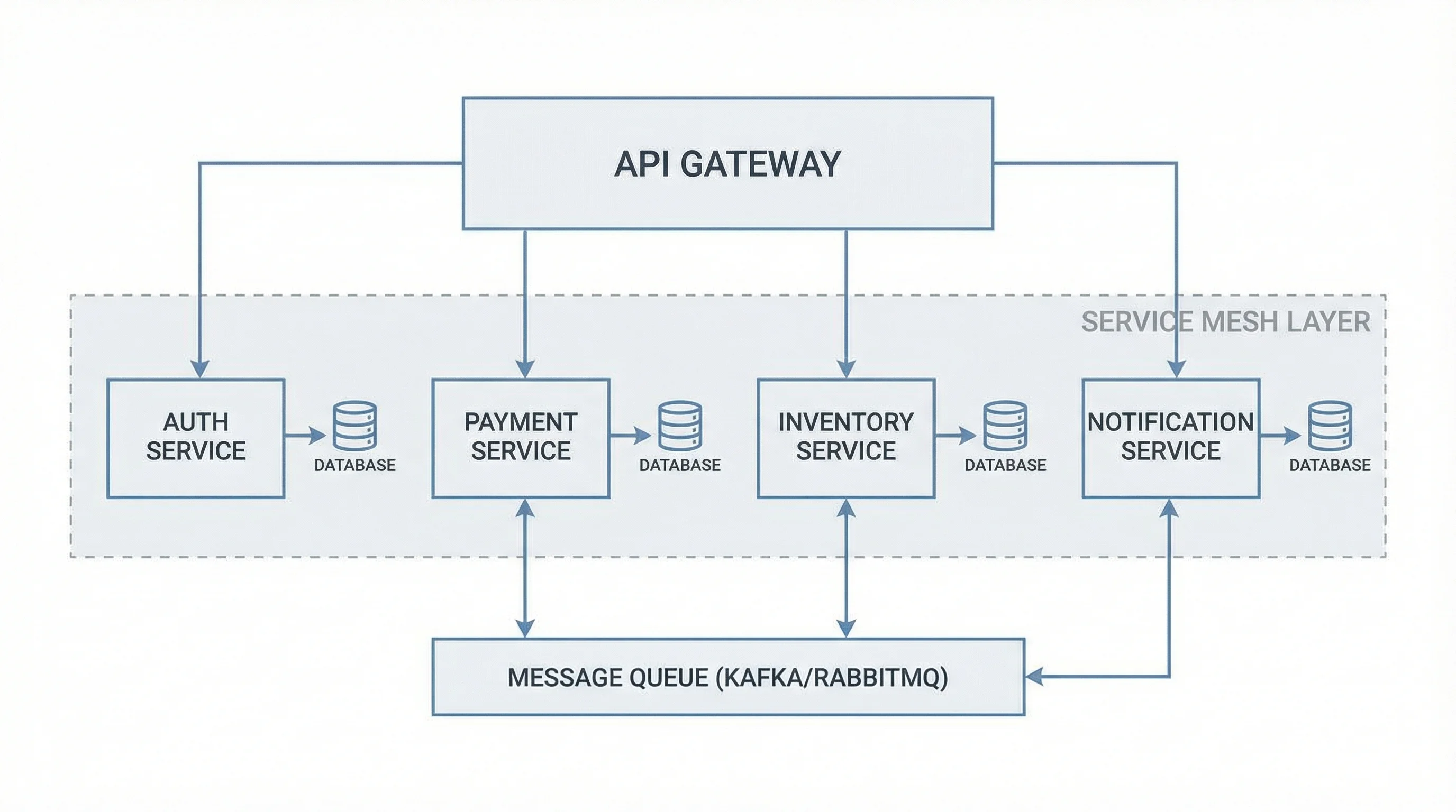
Software Architecture Diagram Generator
Microservices, client-server, cloud, and event-driven system views from a plain-English description.
 Diagrams
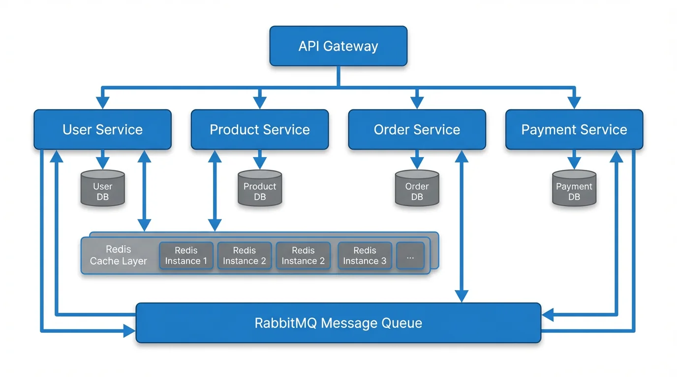
Text to Diagram Generator
Turn any text description into a flowchart, architecture diagram, or process map.
 Diagrams
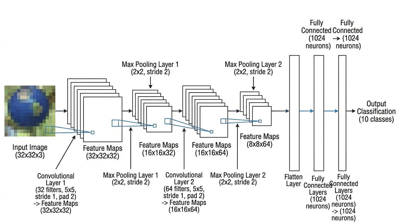
Neural Network Diagram Generator
Draw the model itself: layers, CNNs, and other network architectures.
 Diagrams
AI Flowchart Generator
Describe a process and get a clean flowchart with decisions and branches.