接线图制作工具 接线图
描述您的电气系统,AI将即时生成专业接线图。完美适用于家用电路、汽车电路、工业自动化和暖通空调项目。
接线图生成器
By using ConceptViz, you agree not to generate or edit adult, sexual, explicit, unsafe, or policy-violating content. See Content Policy.
免费试用 ·
接线图将在此处显示
描述您的接线布局并点击生成
接线图示例
浏览不同应用场景的示例,或在上方生成您自己的接线图
家用电路接线
住宅家用电路接线图,展示带断路器的主配电箱、支路、GFCI插座和接地母排。
汽车电路接线
汽车电气系统接线图,包含蓄电池、发电机、启动电机、保险丝盒和照明电路。
工业控制柜
工业控制柜接线图,包含PLC、接触器、电机启动器、热继电器和急停电路。
暖通空调系统接线
暖通空调接线图,包含恒温器接线端、压缩机接触器、冷凝风机、鼓风电机和控制板。
照明电路
住宅照明电路,包含单刀开关、三路开关、调光器、灯具和接线盒。
三相电机接线
三相电机接线图,包含星-三角启动器、定时继电器、热继电器和接触器控制电路。
什么是接线图?
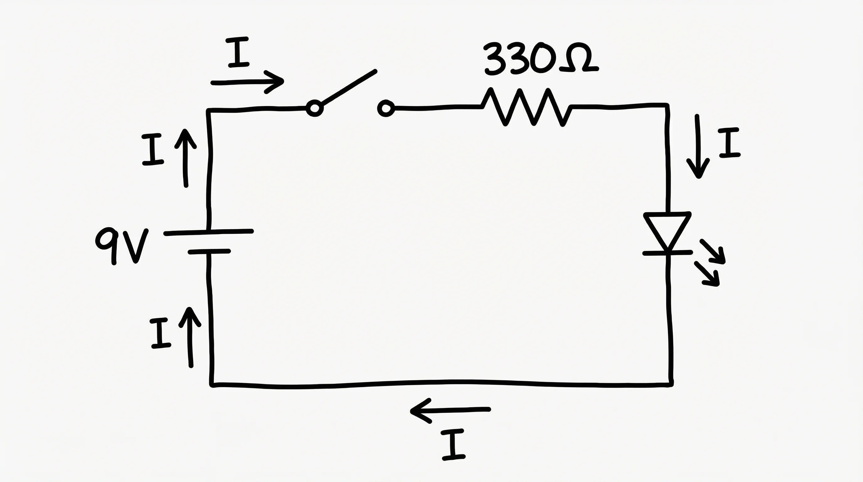
接线图是一种详细的图示,展示电气系统或电路的物理连接和布局。与使用抽象符号的原理图不同,接线图更接近导线、连接器和元器件的实际外观与排列方式。接线图对电工、暖通空调技术员、汽车修理工和工程师至关重要,用于安装、排故和维修电气系统。接线图包含导线颜色、接线端编号、连接器类型以及各元器件间电缆走向等信息。
接线图与原理图的区别
接线图和原理图都用于表示电气电路,但用途各有不同。原理图使用标准化符号展示元器件之间的电气关系,强调功能而非形式。接线图展示物理连接和导线走向,在安装和排故中更具实用性。原理图告诉您电路的功能,接线图告诉您如何搭建或维修它。
接线图的常见应用场景
- 家用电路:配电箱布局、支路、插座和开关接线、GFCI/AFCI保护及接地系统
- 汽车电路:车辆电气系统,包括点火、照明、充电、启动和附件电路
- 工业控制柜:PLC接线、电机启动电路、安全联锁和传感器连接
- 暖通空调系统:恒温器接线、压缩机电路、风机电机连接和控制板图
- 照明电路:开关回路、三路和四路开关配置、调光器安装和灯具接线
- 三相电源:电机接线、星-三角启动器、变频器(VFD)连接和配电图
接线图中的标准电气符号
接线图使用由美国电气制造商协会(NEMA)和国际电工委员会(IEC)等机构定义的标准化符号。常见符号包括:线段表示导线,圆圈表示接线盒,矩形表示断路器和接触器,以及插座、开关、电机和变压器的专用图形。颜色编码同样至关重要——在住宅电路中,通常用红色或棕色表示火线,蓝色表示零线,黄绿色表示接地线(依国标GB规范)。
如何创建有效的接线图
- 从电源出发,向外延伸至各负载,展示从配电箱到设备的完整电路路径
- 一致使用标准符号——根据所在地区和行业,遵循NEC、NEMA或IEC规范
- 标注所有导线的颜色、线径(AWG)和回路编号,便于安装时快速识别
- 在接触器、继电器和电机等所有元器件上标注接线端编号,确保连接无歧义
- 在正确位置标出所有安全设备(断路器、熔断器、热继电器、急停按钮)
- 添加注释,说明与安装相关的特殊要求、力矩规范或法规要求