UML Diagram Generator for Software Design
Generate UML diagrams from a plain-English description. Create class, sequence, use case, activity, state, and component diagrams with correct UML notation — then export your software design diagram, free.
UML Diagram Generator
免费试用 ·
Your UML diagram will appear here
Name the diagram type (class, sequence, use case, etc.) for the best result
UML Diagram Examples
Class, sequence, use case, activity, state, and component diagrams
Class Diagram
Classes with attributes and methods, linked by inheritance, association, aggregation, and composition.
Use Case Diagram
Actors, use case ovals, and a system boundary — the classic way to capture requirements.
Sequence Diagram
Lifelines and messages over time — how objects collaborate to handle a request.
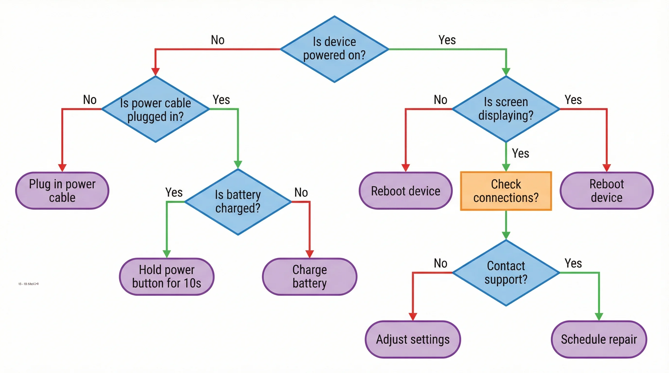
Activity Diagram
Actions, decisions, forks, and swimlanes — a UML flowchart for a process or workflow.
State Machine Diagram
States and labeled transitions show how an object changes over its lifecycle.
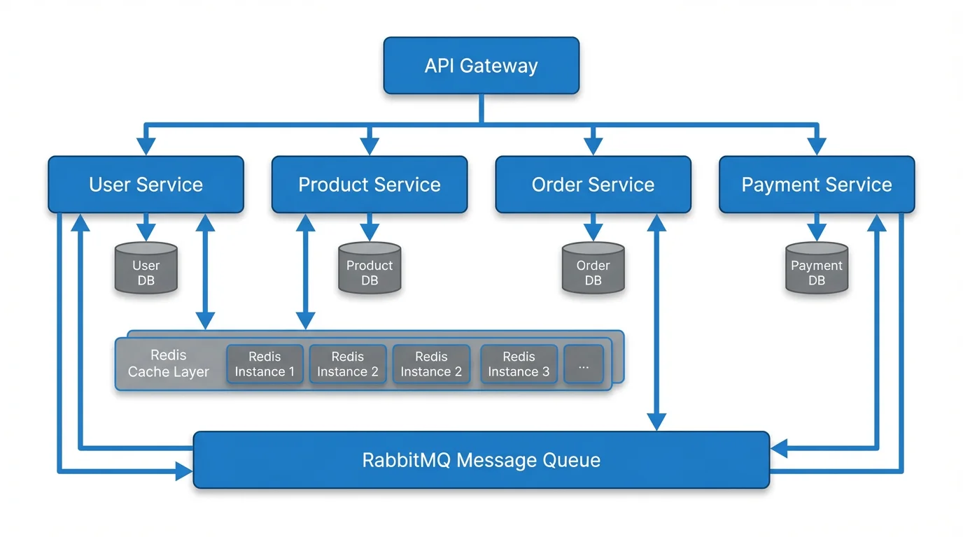
Component Diagram
Components and their interfaces — a high-level map of how a system is assembled.
What is a UML diagram?
UML (Unified Modeling Language) is the standard visual language for modeling software. A UML diagram uses an agreed set of shapes and connectors — boxes for classes, ovals for use cases, lifelines for objects — so that any engineer can read the design the same way. UML lets a team picture a system before they build it: its structure, its behavior, and how its parts interact. This generator turns a plain-English description into a clean, correctly notated UML diagram, so you can capture a design without hand-drawing every box and arrow.
The main UML diagram types
- Class diagram: the structure of a system — its classes, their attributes and methods, and the relationships between them. The most-used UML diagram.
- Sequence diagram: how objects interact over time, with lifelines and the messages passed between them to complete a scenario.
- Use case diagram: the system’s functionality from the user’s point of view — actors, use cases, and a system boundary. Great for requirements.
- Activity diagram: the flow of a process or workflow, with actions, decisions, and parallel branches — essentially a UML flowchart.
- State machine diagram: the states an object moves through and the events that trigger each transition over its lifecycle.
- Component diagram: the high-level building blocks of a system and the interfaces they provide and require — useful for architecture.
How to read a UML class diagram
A class is drawn as a box split into three compartments: the class name on top, its attributes (data) in the middle, and its methods (behavior) at the bottom. A visibility marker precedes each member — plus (+) for public, minus (−) for private, hash (#) for protected. Attributes are usually written name: type, and methods as name(parameters): returnType. Read a class diagram top to bottom for what an object is and does, then follow the connectors to see how it relates to the rest of the system.
Class diagram relationships: association, inheritance, aggregation, composition
- Association: a plain line meaning two classes are linked and one uses the other (for example, an Order references a Customer). Multiplicities such as 1 or 0..* show how many.
- Inheritance (generalization): a hollow triangle arrow pointing to the parent class. A Dog is an Animal, so it inherits the parent’s attributes and methods.
- Aggregation: a hollow diamond for a whole–part relationship where the part can exist on its own — a Team has Players, but the players survive if the team disbands.
- Composition: a filled diamond for a stronger whole–part relationship where the part cannot exist without the whole — a House has Rooms, and the rooms are gone if the house is.
Generate a UML diagram from a description
Describe what you need in plain English — for example, “a class diagram for a library with Book, Member, and Loan classes, where a Member can have many Loans,” or “a sequence diagram for a user logging in through an API gateway.” Name the diagram type you want (class, sequence, use case, activity, state, or component) and list the key elements and how they relate. The generator draws the diagram with correct UML notation, clear labels, and clean connectors, ready to export and drop into a design doc, slide, or pull request.
Using UML in software design
UML is a thinking and communication tool. Sketch a class diagram to agree on the data model before writing code; use a sequence diagram to nail down an API interaction or trace a bug across services; draw a use case diagram to align with stakeholders on scope; reach for an activity or state diagram when the logic is a process or a lifecycle. A diagram does not have to be exhaustive to be useful — even a rough UML view often surfaces missing relationships and edge cases early, when they are cheapest to fix. Generate one in seconds, then refine the description until the design reads right.
常见问题
Related Diagram Tools
 Diagrams
Text to Diagram Generator
Turn any plain-English description into a clean diagram — flows, architectures, and more.
 Diagrams
AI Flowchart Generator
Create flowcharts and decision trees from a description, with clear steps and branches.
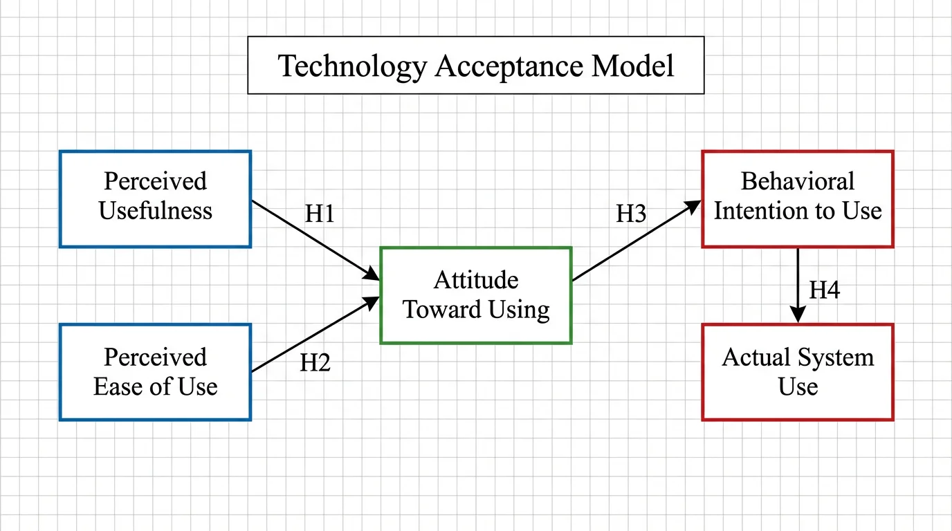 Research
Conceptual Framework Generator
Map variables and relationships into a clear conceptual framework for research.