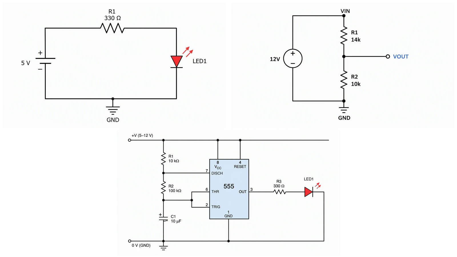
Best Circuit Diagram Software: 12 Tools Compared (2026)
Compare 12 circuit diagram tools for schematics, simulation and PCB work. Prices checked October 2026 on official pages, with free options and who each fits.
The best circuit diagram software depends on what the drawing has to do next. If it must become a PCB, use KiCad or EasyEDA. If it must be simulated, use LTspice or CircuitLab. If it only has to look right in a report, a browser editor such as circuit-diagram.org, DigiKey Scheme-it or draw.io is enough. A text-to-image drafter like ConceptViz is a fourth, smaller option for quick teaching sketches.
This page covers electronic circuit schematics and PCB front ends. For building and automotive wiring, panel drawings and harnesses, read our wiring diagram software guide instead.
Prices and limits were checked on each vendor's own pages on October 11, 2026. Where an official page could not be read, the table says so and shows no number. Confirm before you buy.
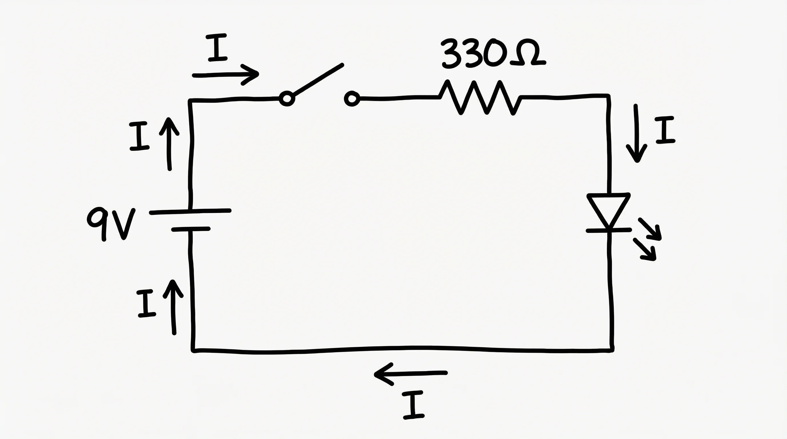
Circuit Diagram Maker
Describe a simple circuit in plain English and get a labeled schematic image for notes, slides and teaching. It is a sketching aid, not EDA software.
Draft a circuit diagram →Quick picks
- Schematic to PCB, free: KiCad (desktop) or EasyEDA (browser and client).
- Simulate analog circuits, free: LTspice.
- Draw and simulate in a browser: CircuitLab.
- Free browser schematics with a parts catalog: DigiKey Scheme-it.
- Clean figure for a report or slide: circuit-diagram.org or draw.io.
- Professional PCB suite: Altium Designer or Autodesk's electronics tools.
- A quick teaching sketch from a sentence: ConceptViz.
Comparison table
The type column uses four labels. Schematic means drawing and editing connections. Simulation means the tool can calculate voltages or waveforms. PCB means it carries the design on to board layout. General means a general diagramming tool with no electrical rules. The learning-curve column is our own judgement, not a vendor claim.
| Tool | Type | Price (checked October 2026) | Free version limits | Platform | Learning curve | Best for |
|---|---|---|---|---|---|---|
| KiCad | Schematic, PCB | Free, GNU GPL v3 (donations welcome) | None stated; the full suite is free | Windows, Linux, macOS | Medium | Open-source boards, hobby to professional |
| EasyEDA | Schematic, PCB | Free plan; paid Individuals plan $19.9/mo, annual billing only | Ads in the editor, 0.5 GB cloud storage, 2 free part builds a month | Web editors, desktop client | Low to medium | Makers who order boards online |
| LTspice | Simulation, schematic | Free | None stated | Windows 10/11, Windows 11 ARM64, macOS | Medium | Analog simulation, filters, power stages |
| CircuitLab | Schematic, simulation | Hacker Lite $79/yr or $16/mo; Pro $399/yr or $39/mo | Free account limits not stated on the membership pages | Browser (Windows, Mac, Linux, iPad) | Low | Students and engineers who want in-browser simulation |
| circuit-diagram.org | Schematic (simulation in beta) | Described as free; no plans listed | None stated | Web editor, desktop download | Low | Clean circuit figures, quick sharing |
| DigiKey Scheme-it | Schematic | Free (named "Free Online Schematic and Diagramming Tool") | None stated | Web | Low | Schematics tied to a parts list |
| draw.io | General | Free, no sign-up | None stated | Web, desktop app | Low | Report figures, block diagrams |
| Visual Paradigm Online | General (circuit diagram type) | Free $0, non-commercial only; Starter $4 per user per month billed annually | Non-commercial use only; watermark-free exports start on Starter | Web | Low | Teams already using it for UML and charts |
| Lucidchart | General (circuit symbols) | Not verified: the pricing page could not be read | Not verified | Web | Low | Teams already on Lucid |
| Altium Designer | Schematic, simulation, PCB | Not stated on the product page | Not stated | Not stated | High | Professional board teams |
| Autodesk electronics tools | Schematic, simulation, PCB | Not verified: Autodesk pages return 403 | Not verified | Not verified | Medium to high | Teams already in the Autodesk ecosystem |
| ConceptViz | Image sketch from text | Credit packs from $4.99 (8 credits); optional subscription from $29.90/mo; 2 trial credits at sign-up | Each image costs 1 credit; no netlist, simulation, or PCB file | Web | Very low | Teaching sketches, notes, early ideas |
A note on what we could not check. We could not open Fritzing's official site during this check, so it is not in the table. The Lucidchart and Autodesk rows are listed because they appear on the first page of Google for the main query, but their prices are left blank instead of copied from search snippets.
What kind of software do you need?
Search results for "circuit diagram software" mix four different jobs, and mixing them is the main reason people pick the wrong tool.
| Job | What you get | Typical tools | Output |
|---|---|---|---|
| Draw a figure | Symbols and wires on a page | circuit-diagram.org, draw.io, Scheme-it | Image, PDF, SVG |
| Capture a schematic | Connections the software understands, with a netlist | KiCad, EasyEDA, Altium | Netlist, ERC (electrical rules check) |
| Simulate | Voltages, currents and waveforms | LTspice, CircuitLab | Plots, SPICE models |
| Lay out a PCB | Footprints, traces, Gerber files | KiCad, EasyEDA, Altium | Manufacturing files |
If you only need the first job, a full EDA suite will cost you hours of library setup. If you need the last one, a drawing tool cannot produce Gerber files. For the method behind a good schematic (symbols, flow direction, labeling), see our step-by-step circuit diagram guide.
The tools one by one
KiCad
KiCad is an open-source suite for schematic capture and PCB layout. Its official page lists the license as GNU GPL v3, says it runs on Windows, Linux and macOS, and says it can produce Gerber and IPC-2581 files. It states no price and asks users to donate. It is the usual answer when a drawing has to become a real board without a license fee. The cost is time: you build or import symbols and footprints, and you assign them correctly before the first board.
EasyEDA
EasyEDA's pricing page says its core features are free. The free Individuals plan lists the Std and Pro editors, unlimited projects, 0.5 GB of cloud storage, two free part builds per month, and ads in the editor and workspace. A paid Individuals plan is $19.9 per month with annual billing only, with more storage and faster part builds. It links to browser editors and a client download. It suits makers who design in the browser and order boards in the same flow.
LTspice
LTspice is Analog Devices' SPICE simulator. The official page says "Fast, Free, Unlimited" and lists downloads for Windows 10/11, Windows 11 ARM64 and macOS. It includes a schematic editor and waveform viewer. It is a simulator first: it will not take your design to a PCB, and its schematics are built to be simulated rather than to look good in a thesis.
CircuitLab
CircuitLab runs in the browser and combines schematic capture with analog and digital simulation. Its membership pages list Hacker Lite at $79 per year or $16 per month, Hacker at $129 per year or $26 per month, and Pro at $399 per year or $39 per month, with Pro marked as authorized for commercial use. An Enterprise plan has a 10-seat minimum. The membership pages do not describe what a free account includes, so we do not state it. The pages list Windows, Mac OS X, Linux and iPad in the browser as supported.
circuit-diagram.org
circuit-diagram.org calls itself a free application for making electronic circuit diagrams. Its homepage lists a web editor, export to scalable vector images, a built-in simulator marked BETA, netlist export, and a community area for sharing circuits. It does not list paid plans. It is a good fit when the goal is a clean figure rather than a board.
DigiKey Scheme-it
DigiKey's Scheme-it is a browser tool whose page title calls it a free online schematic and diagramming tool. The interface offers autosave, project history, a symbol editor, a BOM manager, DigiKey catalog integration, and export to KiCad (beta), PNG, SVG and PDF. It has Quote and Order options for parts, and the page does not say what those cost. The catalog link is the point: a schematic can turn into a parts list.
draw.io
draw.io is a general diagramming tool, free with no sign-up, in the browser or as a desktop app. It has no netlist and no electrical rules checking, so a wrong connection looks the same as a right one. That is fine for a block diagram or a figure you will check by hand, and risky for anything that must be correct by construction.
Visual Paradigm Online
Visual Paradigm lists circuit diagrams as one of many diagram types. Its pricing page shows a Free plan at $0 described as strictly non-commercial, and a Starter plan at $4 per user per month billed annually that adds commercial use rights and watermark-free exports. It makes sense if your team already uses it for UML or charts and you only occasionally need a circuit figure.
Lucidchart
Lucid describes its circuit diagram page as an online editor for pictorial and schematic circuit diagrams with circuit symbols. We could not read its pricing page, so the table shows no figure. Like draw.io, it draws; it does not check electrical rules.
Altium Designer
Altium Designer is a professional schematic and PCB suite. Its product page gives no price and no free trial information in the text we could read, and presents Altium Designer inside several platform offers. If you need it, plan on talking to sales and budget for a learning period.
Autodesk electronics tools
Autodesk lists electronic schematic software that its page describes as covering schematic work and SPICE simulation. Autodesk's pages returned HTTP 403 to us, so we cannot report current plans or prices for its electronics products. Check Autodesk directly before you decide.
Where ConceptViz fits, and where it does not
ConceptViz's circuit diagram maker turns a plain-English description into a labeled image of a circuit. It is for teaching sketches, lab notes, slides and early ideas. It is not EDA software. It does not produce a netlist, a simulation, a PCB, or a file you can edit in a schematic editor. Downloads are a PNG image, or a traced SVG with paid credits.
It needs a signed-in account, and each image costs 1 credit. New accounts get 2 trial credits that expire after 7 days. One-time credit packs start at $4.99 for 8 credits, and an optional subscription starts at $29.90 per month.
Here is what that looks like in practice. We ran three prompts through the tool's own analysis step and image step, one pass each, and checked every symbol, connection and value by hand.
Test 1: LED with a current-limiting resistor
Prompt: "Draw a 5V LED indicator circuit with a current limiting resistor for about 10mA."
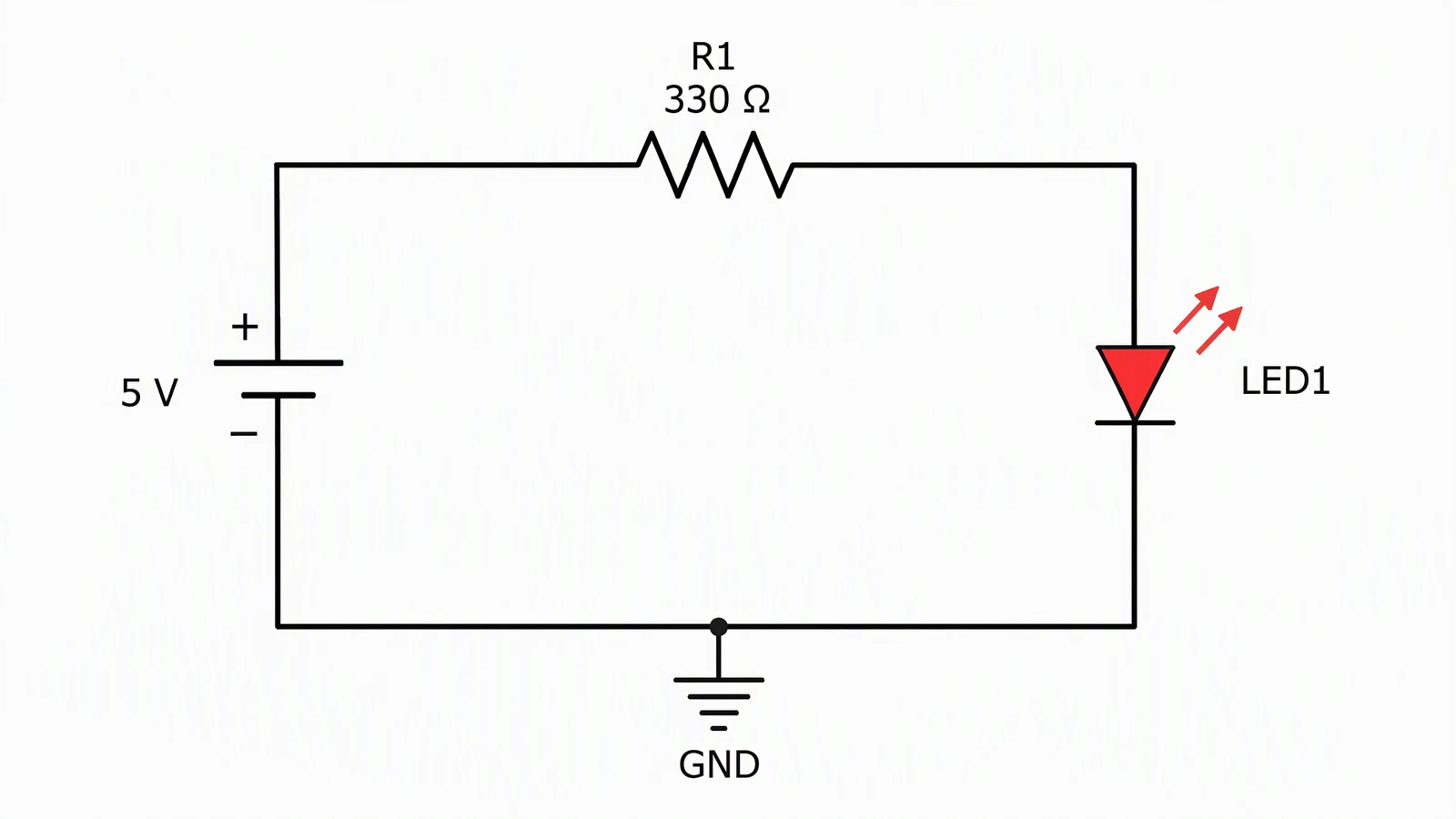
Generated from the prompt above. Checked by hand: the long plate of the source is positive and feeds R1, the LED triangle points from the resistor side toward ground, the emission arrows point away from the LED, and the loop closes. At 330 ohms the tool's own note gives about 9 mA, assuming a roughly 2 V red LED. Nothing needed fixing.
Test 2: Resistor divider
Prompt: "Create a 12V to 5V resistor divider and label VOUT."
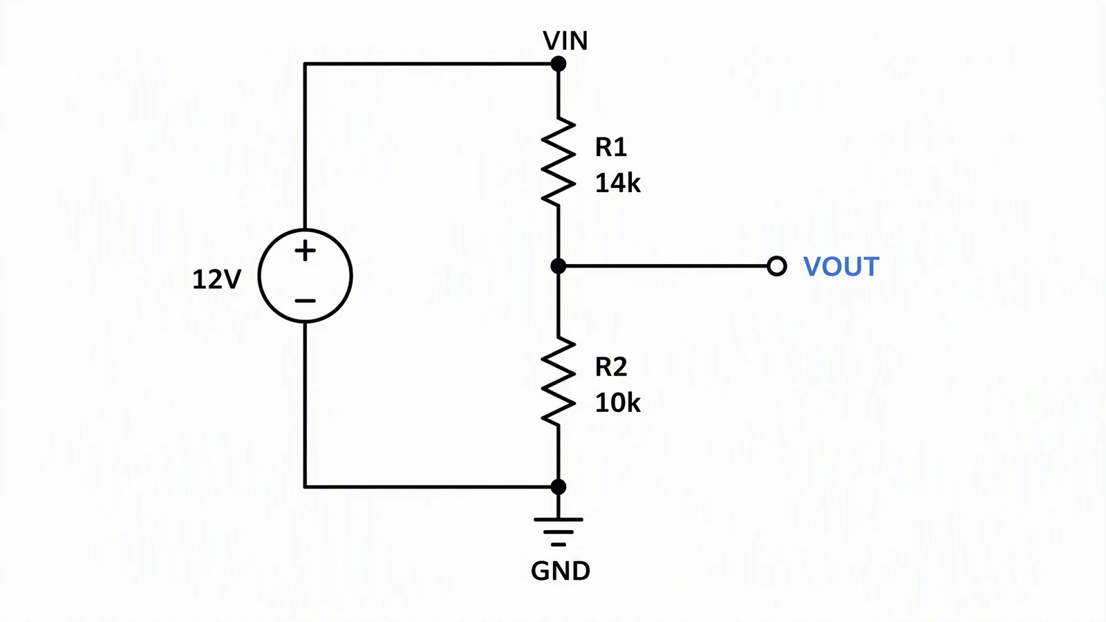
Generated from the prompt above. Checked by hand: R1 runs from the positive rail to the VOUT node, R2 from VOUT to ground, and the source returns to ground. The ratio is right: 12 V x 10k / (14k + 10k) = 5.0 V. Two things to fix before using it: 14k is not a standard E24 resistor value (it exists in the E96 series), and VOUT is labeled without the 5 V figure, in a different color from the other labels.
Test 3: 555 astable LED flasher
Prompt: "Draw a 555 timer astable circuit that blinks an LED at about 1 Hz."
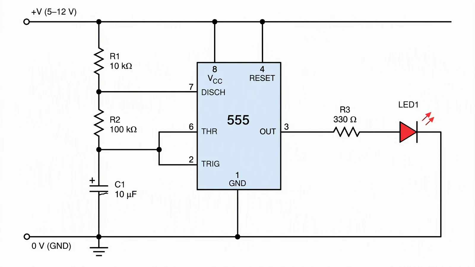
Generated from the prompt above. The tool classified this request as outside its verified schematic templates (it handles a small set such as LED indicators and dividers), so the values below were not in our prompt and were chosen by the image step. Checked by hand: the pin functions and connections are right. Pins 8 and 4 go to the supply, 1 to ground, R1 sits between supply and pin 7, R2 between pin 7 and pins 6 and 2 which are tied together, C1 from that node to ground with the plus mark on the correct side, and pin 3 drives the LED through R3 to ground. Problems: with R1 10k, R2 100k and C1 10 uF the frequency is about 0.69 Hz (1.44 / ((R1 + 2 x R2) x C)), not the requested 1 Hz; the top supply rail runs past pin 4 and ends open on the right; and the optional pin 5 capacitor is not drawn. Recalculate the values yourself before building.
What the tests say: on three simple circuits the symbols and connections were correct, and the issues were values and finishing details. That is evidence for simple teaching circuits, not a promise for complex ones, and the 555 case shows why you must check values you did not supply. If you need to edit the result, run a netlist, or send it to a board house, use one of the tools above.
For a more general schematic from text, the schematic diagram maker covers broader scientific and engineering diagrams. For electrical one-line drawings, see the single-line diagram generator.
How to choose
| If you are... | Start with | Why |
|---|---|---|
| A student with a lab report due | circuit-diagram.org or CircuitLab | Quick, browser-based, clean output |
| A hobbyist building a first board | KiCad or EasyEDA | Free path from schematic to Gerber files |
| Designing a filter or power stage | LTspice | Free, serious analog simulation |
| Writing slides or a worksheet | draw.io, or a text-to-image sketch | You only need a picture |
| Ordering parts as you design | DigiKey Scheme-it | Catalog and BOM tools in the page |
| On a professional board team | Altium Designer or Autodesk tools | Team libraries, rules, manufacturing output |
Whatever you pick, check the finished drawing against the real parts: pin numbers on the datasheet, polarity of diodes and electrolytic capacitors, and the return path of every loop. A drawing that looks tidy can still be wrong, and AI or not, the check is yours.
Frequently asked questions
What is the best free circuit diagram software?
For a drawing that must become a PCB, KiCad is free under the GNU GPL v3 and runs on Windows, Linux and macOS. For simulation, LTspice is free. For a quick figure in the browser, circuit-diagram.org and draw.io are free. Which is best depends on whether you need a board, a simulation or just a picture.
What is the difference between circuit diagram software and PCB design software?
Circuit diagram software draws connections between components. PCB design software carries those connections on to a physical board layout with footprints, traces and manufacturing files. Suites such as KiCad and EasyEDA do both; drawing tools such as draw.io do only the first.
Can I simulate a circuit in the same tool I draw it in?
Some tools can. LTspice and CircuitLab combine a schematic editor with simulation, and circuit-diagram.org lists a simulator in beta. General diagramming tools such as draw.io do not simulate.
Is there a free online circuit diagram maker with no install?
Yes. circuit-diagram.org and DigiKey Scheme-it run in the browser, draw.io runs in the browser or as a desktop app, and EasyEDA offers browser editors. Check each tool's terms for limits such as ads or storage.
Can an AI circuit diagram maker replace KiCad or EasyEDA?
No. A text-to-image drafter produces a picture, not a netlist, so it cannot check connections, run a simulation or generate PCB files. It can save time on a teaching sketch, and the result still needs to be checked against the real parts.
Does ConceptViz export an editable schematic or a netlist?
No. The circuit diagram maker produces an image. You can download it as a PNG, or convert it to a traced SVG with paid credits, but neither is a schematic with real components. It does not export a netlist, a simulation file or an editable schematic.
Is this guide about wiring diagrams for houses and cars?
No. This guide covers electronic circuit schematics and PCB front ends. For building, panel and automotive wiring software, see the electrical wiring diagram software guide on this site.
Circuit Diagram Maker
Turn a one-sentence circuit description into a labeled schematic image, then check each connection and value before you use it.
Try the circuit diagram maker →Categories
More Posts
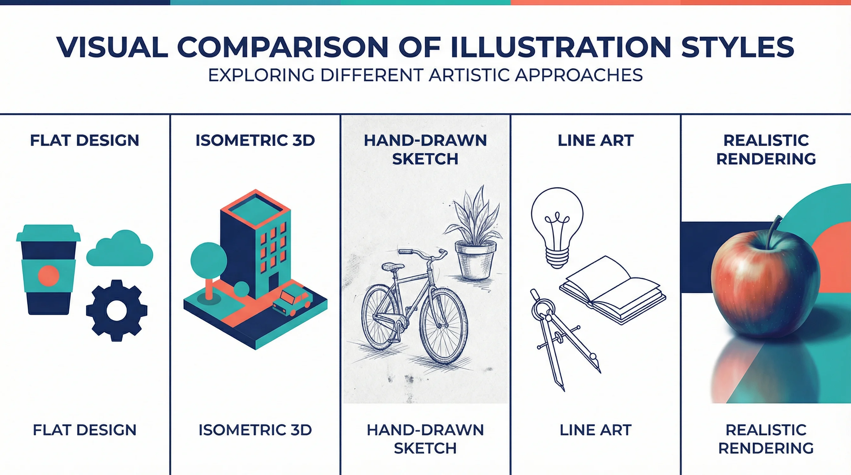
15 Illustration and Infographic Design Styles Explained (2026)
Explore 15 illustration and infographic design styles with examples: flat, isometric, 3D, hand-drawn, minimalist, vector, cartoon, line art and more.
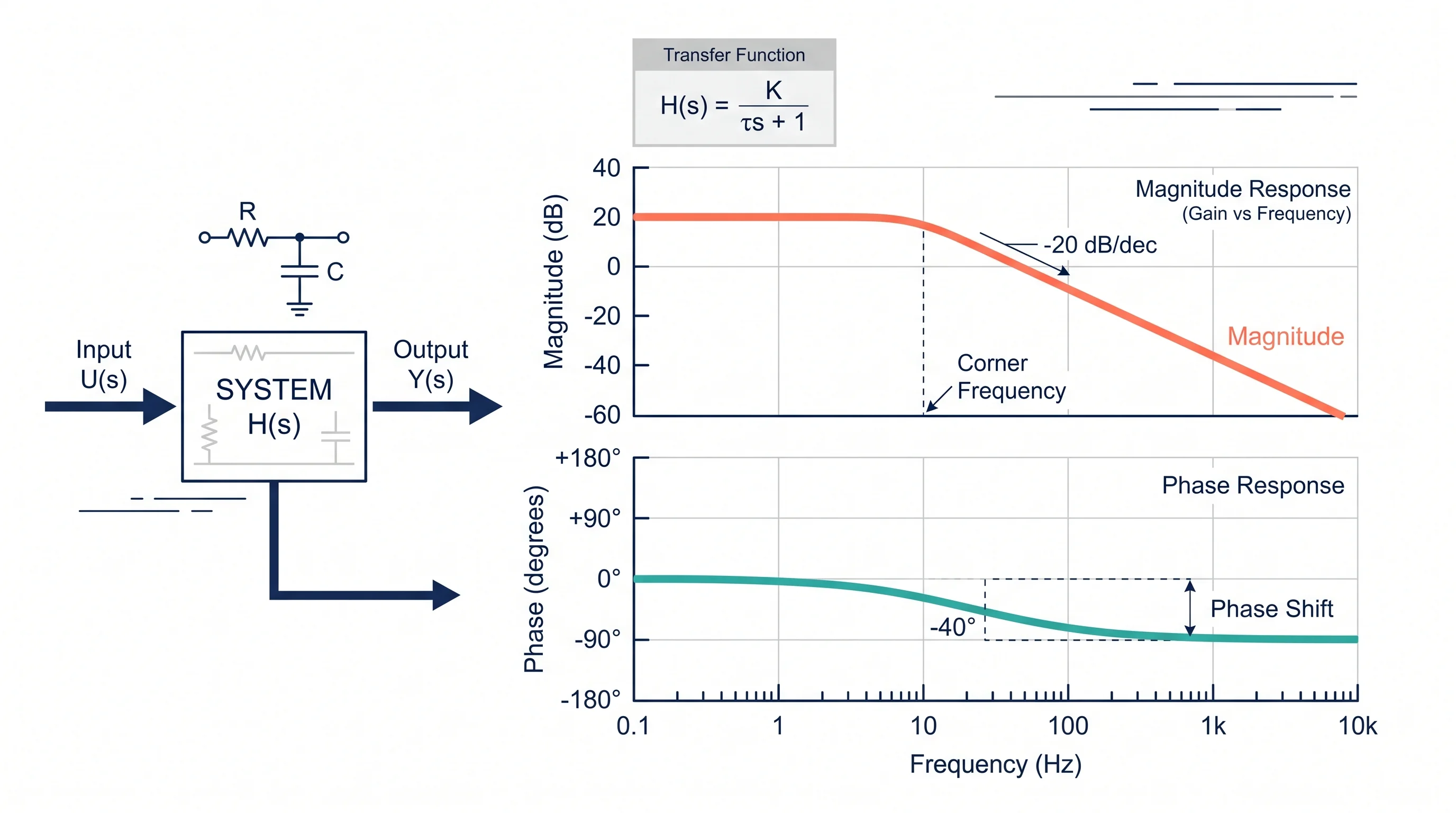
Bode Plot Generator Guide: Make Magnitude and Phase Plots from a Transfer Function
Learn how to use a Bode plot generator, enter transfer functions correctly, read magnitude and phase plots, and avoid common frequency-response mistakes.
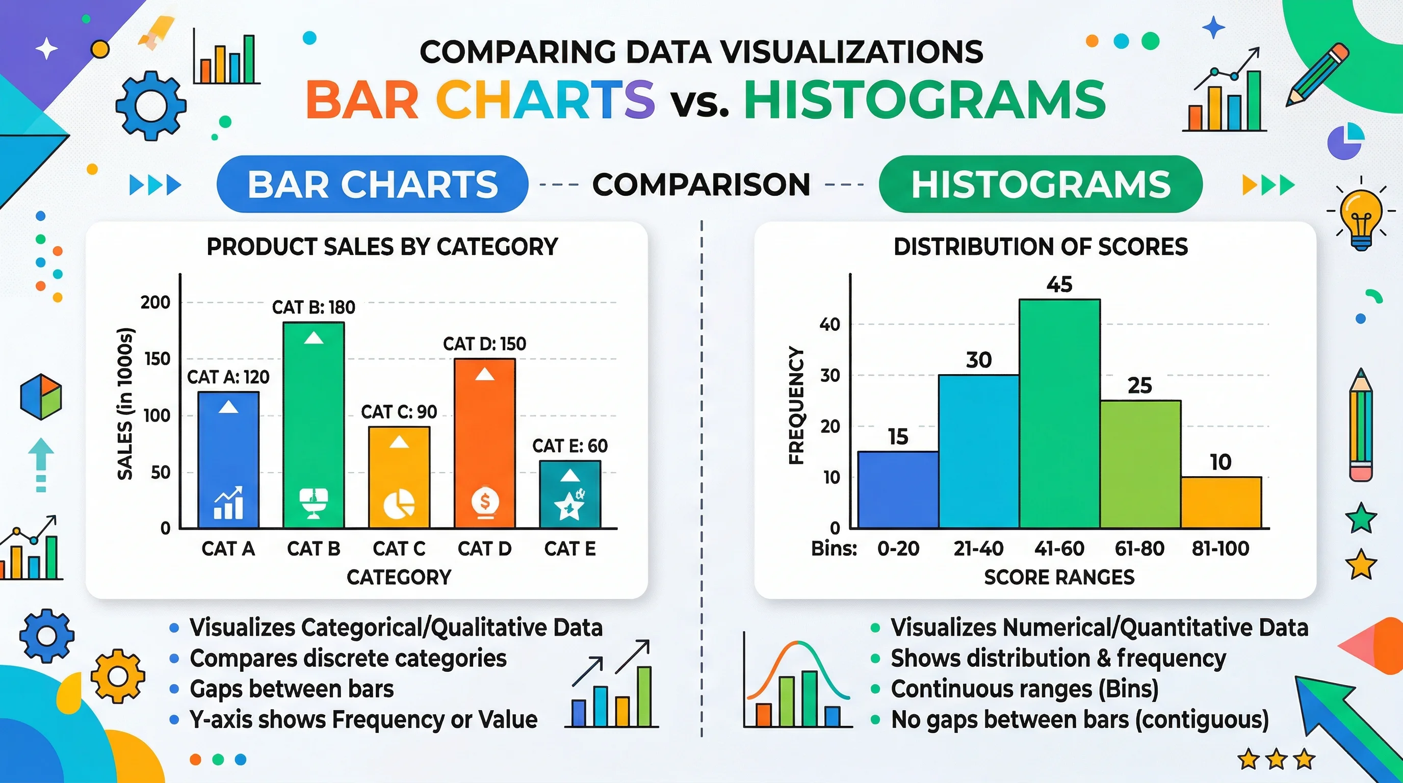
Bar Chart vs Histogram: Key Differences Explained
Learn the real difference between bar charts and histograms with clear examples. Covers when to use each, common mistakes, and how to create both quickly.