Systems Engineering V-Model Diagram Generator for Requirements, Verification and Validation
Generate a systems engineering or software testing V-model diagram from a text prompt, with an exact diagram redrawn from the FHWA ITS Vee.
Create Your V-Model Diagram
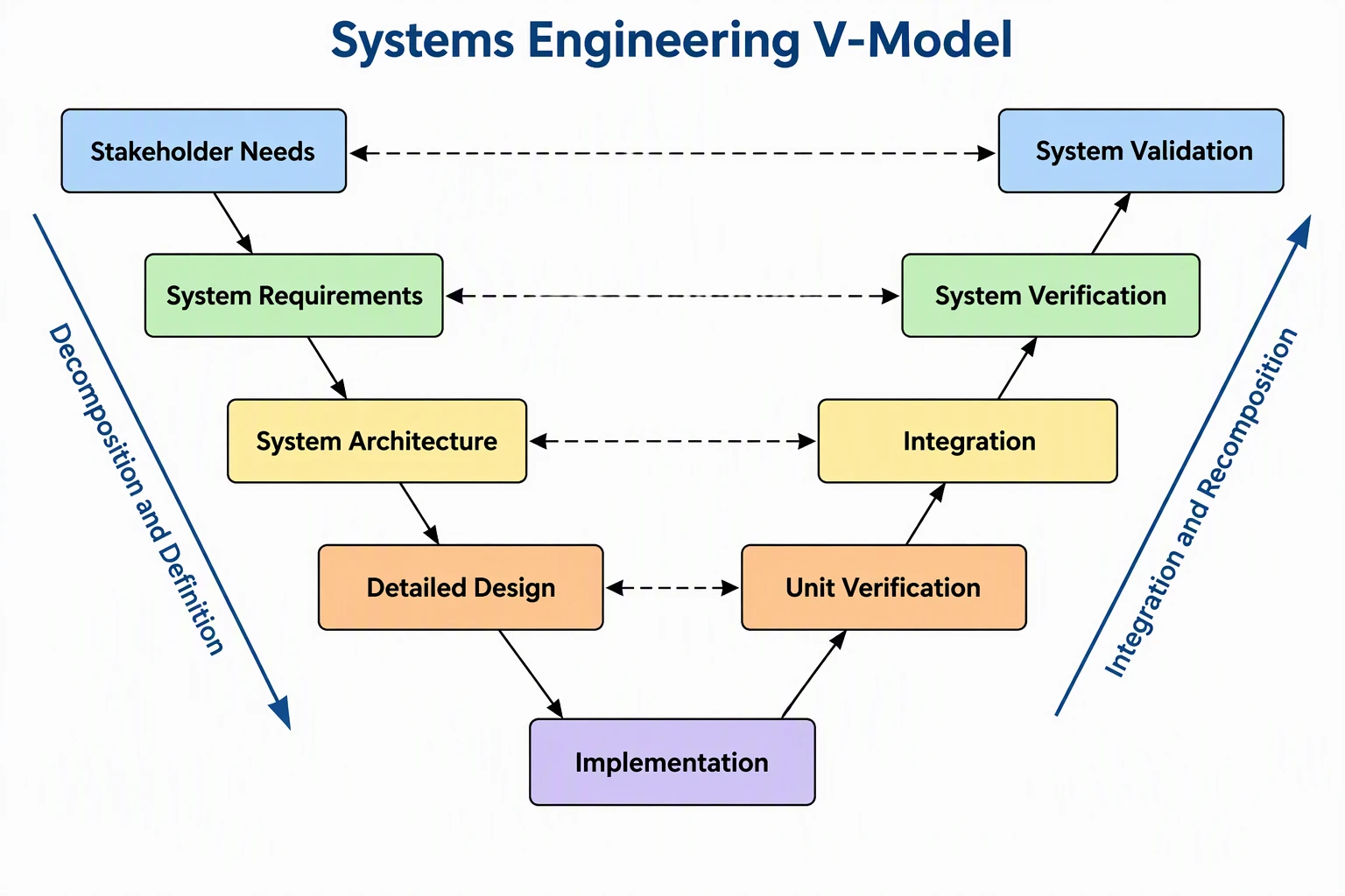 Example: Systems engineering VView full size
Preview is free on this page ·
Your V-model diagram will appear here
AI diagrams are drafts. Check every label and every left-right pairing before use.
V-Model Diagram Examples
One exact diagram drawn in code from the FHWA Vee, plus three AI diagrams with their known flaws noted. AI diagrams need human review.
The FHWA systems engineering Vee for an ITS project (exact diagram)
Drawn in code, not by AI, from the Vee in the FHWA guide Systems Engineering for ITS (section 3.3.1, checked October 2026). Three pairings are drawn exactly as FHWA shows them: Concept of Operations with Validation (Validation Plan), Requirements with Deployment and Acceptance (Acceptance Criteria), and Requirements with Integration and Verification (Verification Plan(s)). FHWA draws no dashed line from Design and Specifications, so we do not invent one. The dark ovals are FHWA decision gates, placed to match the FHWA figure (none below Software and Hardware Implementation). The diagram is redrawn, not copied, and it is a planning aid.
Classic systems engineering V (AI diagram)
AI-generated from the prompt shown. We checked every label and pairing: Stakeholder Needs pairs with System Validation, System Requirements with System Verification, System Architecture with Integration, and Detailed Design with Unit Verification, and the label spelling is correct on this attempt. Our first attempt misspelled "Decomposition" on the side arrow, so we regenerated it. Known flaws: this four-level pairing is a common generic teaching layout, not the FHWA figure above, and level names differ between handbooks; the right-side box "Unit Verification" is our wording, not a fixed standard term; and the layout is a draft, not a project plan.
Software testing V-model (AI diagram)
AI-generated from the prompt shown. The four pairings are right: Requirements Analysis with Acceptance Testing, System Design with System Testing, Architecture Design with Integration Testing, Module Design with Unit Testing. Known flaws: only two of the dashed lines carry a caption ("Validation" on requirements to acceptance, "Verification" on module design to unit testing), so the captions look inconsistent; the arrow between Coding and Unit Testing is double-headed although the flow only goes up; and the colors do not mean anything. Some textbooks label the whole left side verification and the whole right side validation, which is a loose shorthand, so check the term your course or standard uses.
V-model for a traffic signal project (AI diagram)
AI-generated from the prompt shown. The pairings match what we asked for: Concept of Operations with System Validation, System Requirements with System Verification and Deployment, High-Level Design with Subsystem Verification, Detailed Design with Unit and Device Testing, and every label is spelled correctly. Known flaws: the arrow between Subsystem Verification and Unit and Device Testing is double-headed although the flow only goes up; the arrow from the bottom Hardware and Software Implementation box to Unit and Device Testing points into the implementation box, which is backwards, because the flow should go from implementation up to unit testing; the step names (such as "High-Level Design" and "Unit and Device Testing") come from our prompt and are not the labels of the current FHWA figure, which names fewer levels; and a real signal project would add planning, decision gates and operations steps.
For the structure of the software itself, use the Software Architecture Diagram Generator. For process steps and flows, see the Process Flow Diagram Generator. For an engineering example with an exact diagram, see the Control Panel Wiring Diagram Generator.
Source (checked October 2026): FHWA, Systems Engineering for ITS, Vee Overview.
What the systems engineering V-model is
The V-model is a way to draw a development process as a V. The left side goes down from the broadest view of the problem to detailed design, the bottom is where the system is built, and the right side goes back up as the pieces are integrated and checked. Each step on the way up is tied to a step on the way down, so every need and requirement has a matching check. Teams use it in systems engineering, embedded and automotive work, defense, transportation and software to plan tests early, explain a project to a customer, or teach the logic of requirements and verification.
The FHWA Vee: the exact diagram on this page
- The exact diagram follows the Vee in the Federal Highway Administration guide Systems Engineering for ITS (intelligent transportation systems), section 3.3.1, which we checked in October 2026. We redrew it in code rather than copying the picture.
- Left side, called decomposition and definition: regional ITS operations planning and project identification and scoping sit above the Vee, then project planning, concept of operations, requirements, and design and specifications.
- Bottom: software and hardware implementation, the actual build or procurement of hardware and coding or procurement of software.
- Right side, called integration and recomposition: integration and verification, deployment and acceptance, validation, and then operations and maintenance and retirement or replacement above the Vee.
- Dashed lines in the FHWA figure: a validation plan links concept of operations to validation, acceptance criteria link requirements to deployment and acceptance, and verification plans link requirements to integration and verification. FHWA decision gates are the milestones where stakeholders decide whether the project can move on to the next step.
Verification vs validation on the V
- Verification asks whether you built the system right: does it satisfy the requirements? Validation asks whether you built the right system: does it meet the stakeholder needs and objectives?
- In the FHWA Vee, integration and verification checks that all requirements have been satisfied, and validation, after deployment and acceptance, checks that the system meets the needs and objectives originally intended.
- That is why requirements pair with verification, and the concept of operations, which records the user needs, pairs with validation. Many software texts simplify this and call all testing on the right side validation, or the whole left side verification. Both usages exist, so state which definition your document uses.
The software testing V-model
- Searches for "v model" often mean the software testing version. A common teaching layout pairs requirements analysis with acceptance testing, system design with system testing, architecture design with integration testing, and module design with unit testing, with coding at the bottom.
- The point is the same as in systems engineering: you write the test plan for each level while you write the level on the left, not after the code exists. Names differ between courses and standards, and some versions have fewer or more levels, so use the layout your team or syllabus defines.
- Critics note the V-model is sequential and works best when requirements are stable. It does not forbid iteration, but a plain V diagram does not show it.
How to generate a V-model diagram from text
- Name the diagram type first: systems engineering V, software testing V, or a V for your own domain such as automotive or transportation.
- List the left-side boxes from top to bottom, the single bottom box, and the right-side boxes from bottom to top, using the exact words you want on the labels.
- State the pairings you want: which left box connects to which right box with a dashed arrow. Without this the AI may pair boxes by position, which is not always what your source says.
- Ask for short English labels, a title, and no brand names. Generate, then check every label spelling and every pairing against your source, and re-prompt for what is wrong.
Exact diagram vs AI diagrams on this page
The exact diagram is drawn in code, so every box, label and dashed line is placed on purpose, following a named official source. The three AI diagrams were generated from the prompts shown. We checked each for left-to-right pairings, the position of verification and validation, and label spelling, and each caption lists the flaws we found. AI output is useful for a quick draft, but labels can be misspelled and pairings can drift. A diagram from this page is a planning and teaching aid. It is not a project plan, a compliance document or a replacement for the standard or handbook your organization follows.
Sources and further reading
FHWA, Systems Engineering for ITS, section 3.3.1 (Vee Overview) and section 3.2, checked October 2026. ISO/IEC/IEEE 15288 defines life cycle processes, including verification and validation processes; it does not define the V diagram. Use the current edition from the publisher. Diagrams from this page do not claim compliance with any standard.
Frequently Asked Questions
Related Engineering Tools
 Research
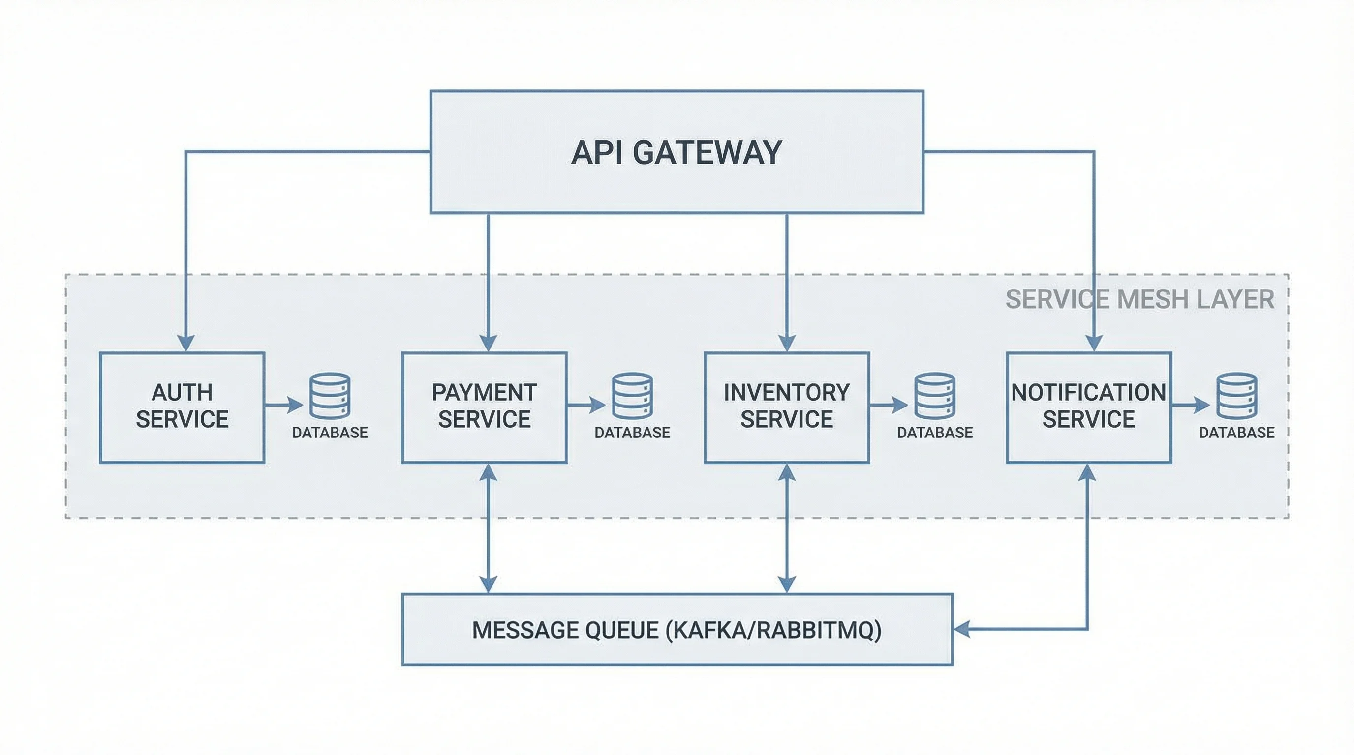
Software Architecture Diagram Generator
Create software architecture diagrams including microservices, MVC, client-server, and cloud architectures.
 Engineering
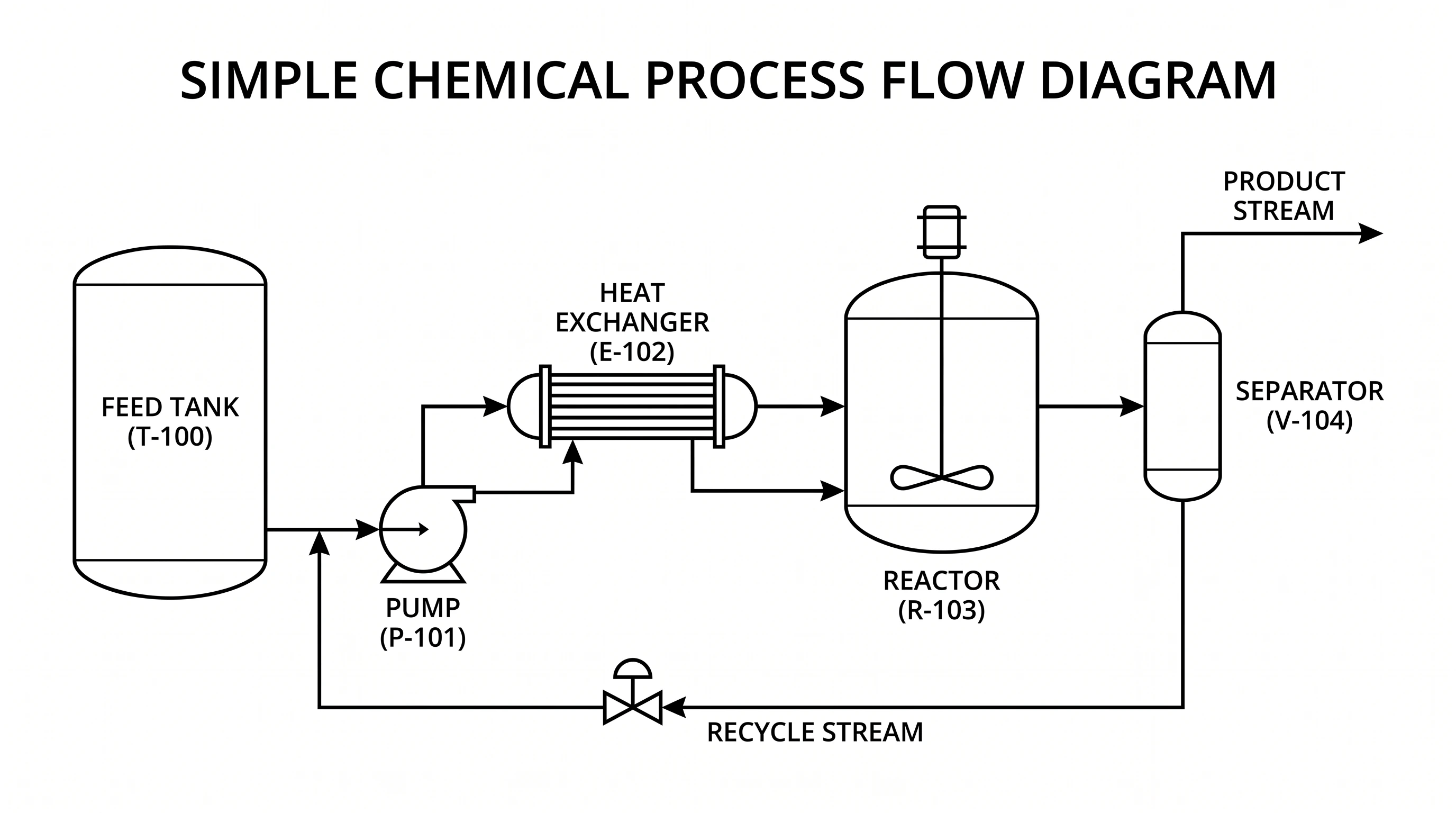
Process Flow Diagram Generator
Generate process flow diagrams for chemical, manufacturing, and utility processes.
 Engineering
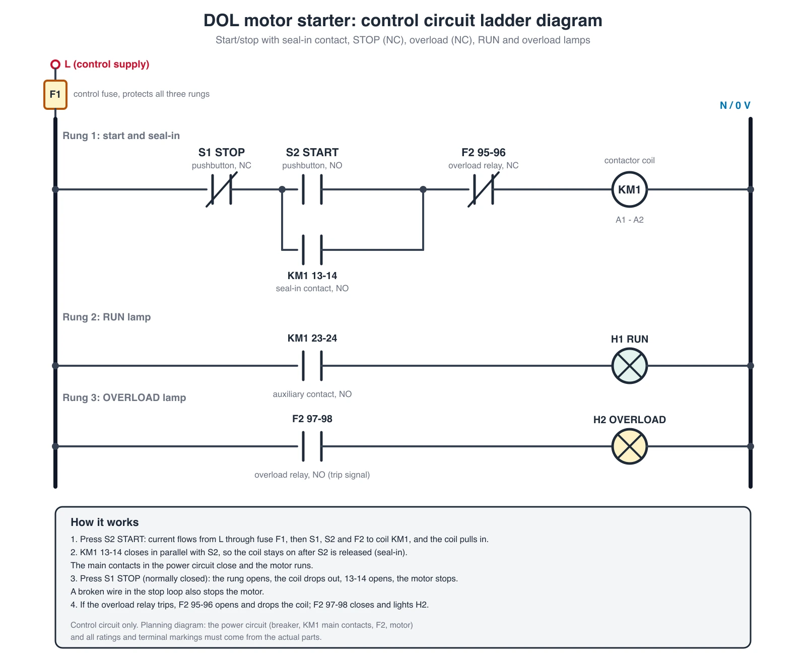
Control Panel Wiring Diagram Generator
Generate control panel wiring diagrams: DOL motor starters, PLC 24V DC inputs and outputs, and panel layouts, with an exact ladder diagram.