Pulley Diagram Generator for Fixed, Movable & Compound Pulleys
Generate labeled pulley diagrams — fixed pulleys, movable pulleys, compound pulley systems, and block-and-tackle rigs. Show the rope, load, effort force, axle, and mechanical advantage in a clean, textbook-style diagram. Free.
AI Pulley Diagram
Free to try ·
Your pulley diagram will appear here
AI-generated — review labels and mechanical advantage for accuracy before using in class
Pulley Diagram Examples
Fixed pulleys, movable pulleys, compound systems, and block-and-tackle rigs
Fixed Pulley
A fixed pulley changes the direction of the effort force but not its magnitude — mechanical advantage = 1.
Movable Pulley
A movable pulley halves the effort needed to lift a load — mechanical advantage = 2.
Compound Pulley System
Combining fixed and movable pulleys multiplies mechanical advantage — four rope segments give MA = 4.
Block and Tackle
A block and tackle uses two multi-sheave blocks and multiple rope segments to lift very heavy loads with little effort.
Mechanical Advantage Comparison
Fixed vs. movable pulley side by side — showing how MA changes with pulley type.
Blank Pulley Worksheet
An unlabeled version for worksheets and quizzes — students fill in rope, load, effort, axle, and wheel.
What is a pulley diagram?
A pulley diagram is a labeled technical drawing that shows how a pulley system transmits force. It identifies the wheel (with its grooved rim), the axle it rotates on, the rope (or belt) running over the groove, the load being lifted or moved, and the effort force applied by the user. A good pulley diagram also notes the mechanical advantage — how many times the pulley multiplies the input force — so it is clear how much effort is needed relative to the load. Pulley diagrams appear in physics textbooks for Newton's laws, force and work, and simple machines units.
The three main types of pulleys
- Fixed pulley: the axle is attached to a fixed support (ceiling, beam, or post). The rope runs over the wheel. A fixed pulley does not multiply force — mechanical advantage = 1 — but it changes the direction of the effort, allowing you to pull down to lift a load up.
- Movable pulley: the axle is attached to the load, not to a fixed support. Two rope segments support the load, so the mechanical advantage = 2, meaning you lift with half the force. The trade-off is that the rope must move twice as far as the load.
- Compound pulley (block and tackle): a combination of fixed and movable pulleys. Mechanical advantage equals the number of rope segments supporting the movable block. Four segments give MA = 4; six segments give MA = 6. Block-and-tackle systems are used on sailing ships, cranes, and construction equipment.
Key parts labeled on a pulley diagram
- Wheel: the circular disk with a grooved rim that guides the rope. It is the rotating part of the pulley.
- Axle: the pin or shaft at the center of the wheel. In a fixed pulley the axle is attached to a support; in a movable pulley the axle is attached to the load.
- Rope (or cable): runs in the groove of the wheel. The tension in the rope transmits the force from where you pull to the load.
- Load (resistance force): the weight or object being lifted or moved, acting downward due to gravity.
- Effort (applied force): the force exerted by the user or motor to move the load. In a fixed pulley it equals the load; in a movable pulley it is halved.
- Mechanical advantage (MA): the ratio of load force to effort force. Calculated as the number of rope segments supporting the movable block.
How mechanical advantage is calculated
Mechanical advantage (MA) for a pulley system equals the number of rope segments directly supporting the load (the movable block). Count every rope segment that is attached to or passes under the movable pulley or load block — each segment carries an equal share of the load. A single fixed pulley has one segment under the load, so MA = 1. A single movable pulley has two segments, so MA = 2. A compound system with three movable pulley wheels and one fixed wheel can have six supporting segments, giving MA = 6. The effort required is Load ÷ MA, and the rope must be pulled MA times as far as the load moves (the work-energy principle — you gain force but give up distance).
Fixed pulley vs. movable pulley
The key difference is where the axle is mounted. A fixed pulley's axle is bolted to a support, so the wheel spins but doesn't move — it only redirects the rope. A movable pulley's axle is free to move up and down with the load, so the wheel rises as you pull. Because two rope segments share the load on a movable pulley, each carries only half the weight, halving the effort needed. Combining both types in a compound system lets you stack mechanical advantages and lift loads many times heavier than the applied effort.
How to generate a labeled pulley diagram
- Type a description of the pulley system you need — fixed, movable, compound, or block-and-tackle.
- Specify what to label: rope, load, effort, axle, wheel, mechanical advantage, rope segments, or force directions.
- For worksheets, ask for a blank (unlabeled) version so students can fill in the parts.
- Download the image and drop it into your slides, notes, or printed worksheet.
Frequently Asked Questions
Related Physics Tools
 Physics
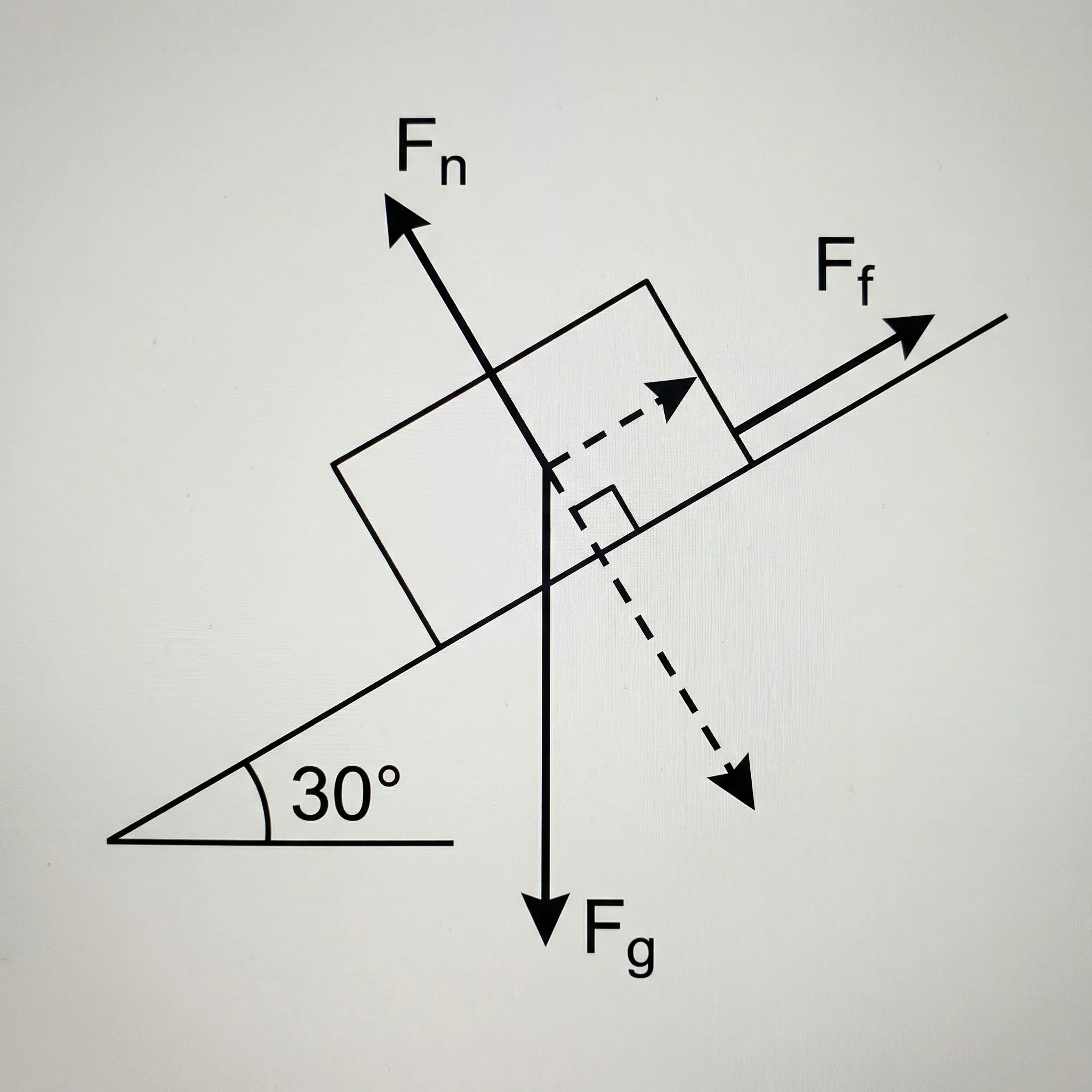
Free Body Diagram Generator
Create labeled force diagrams with weight, normal force, friction, tension, and applied-force vectors for any physics scenario.
 Physics
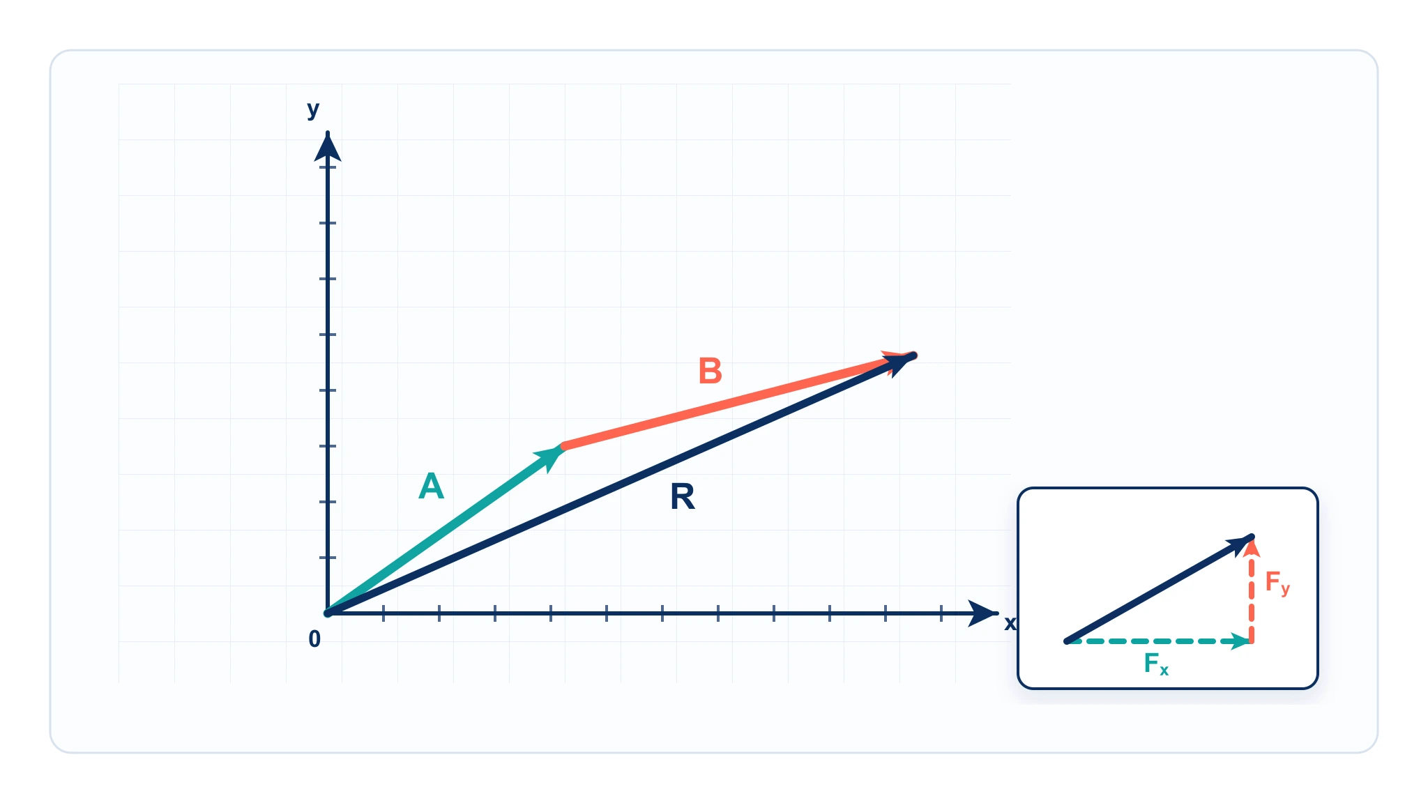
Vector Diagram Physics Maker
Draw vector arrows, components, and resultants with precise angles and scale for physics problems.
 Physics
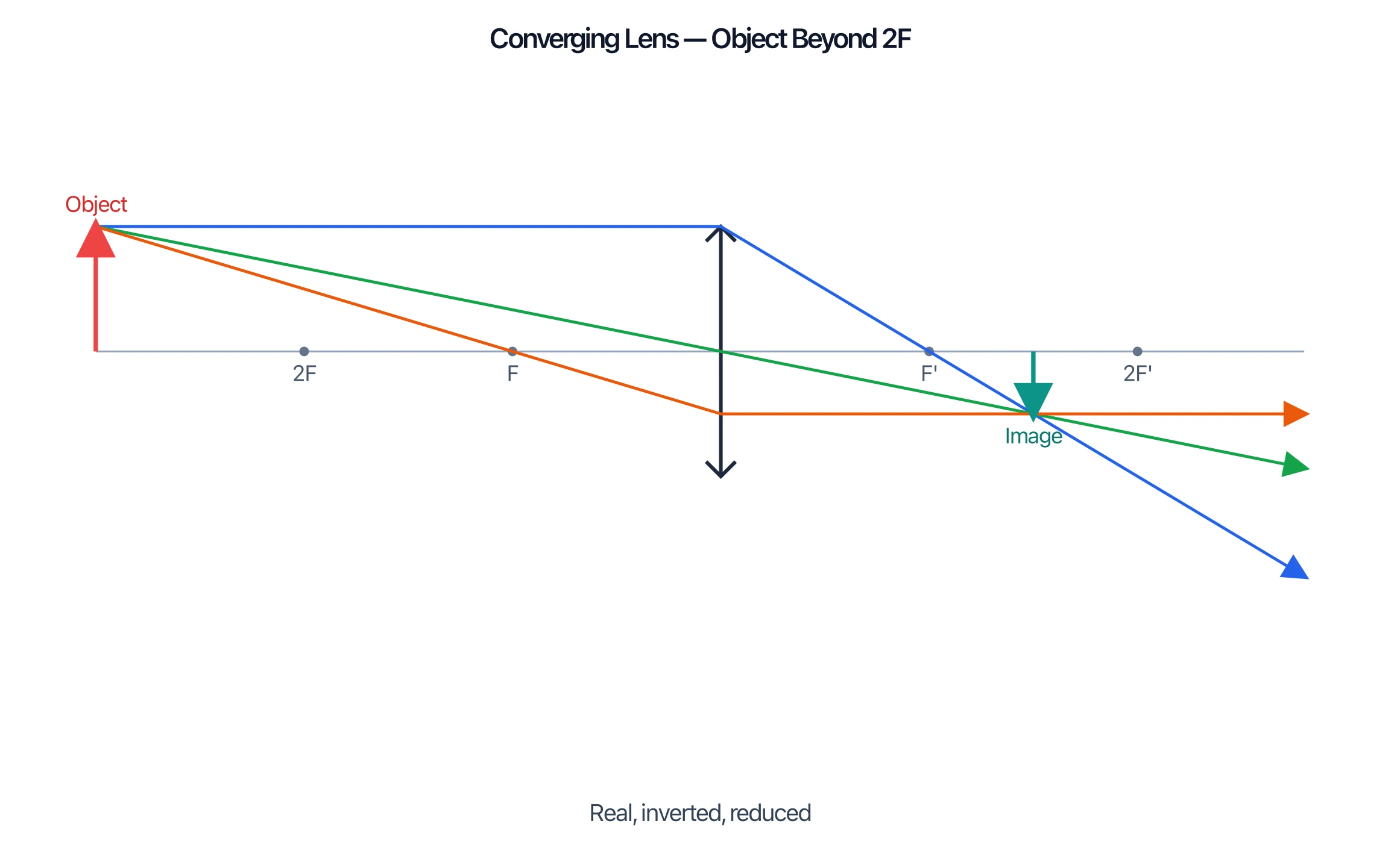
Ray Diagram Generator
Draw accurate ray diagrams for converging and diverging lenses and concave and convex mirrors.