How to Make an HVAC Diagram: System Schematic, Not Wiring
Make an HVAC system schematic: pick the drawing type, list equipment and flow, then label it clearly. Not a thermostat sticker and not a shop wiring diagram.
Describe the plant — AHU, refrigerant loop, or hydronic schematic — and get a first-pass system diagram. Not a stamped as-built and not a thermostat pinout.
Start with this diagram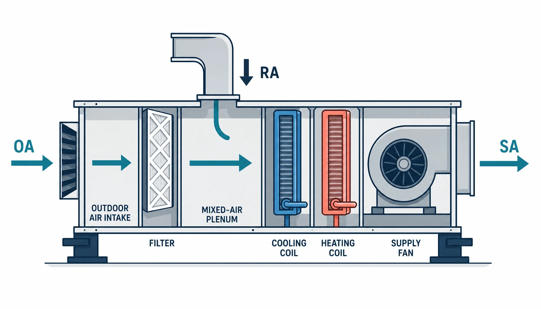
Most “HVAC diagram” searches are looking at how the plant works: outdoor air into an AHU, refrigerant around a split system, chilled water from a chiller to coils. That drawing is a system schematic. It is not the Honeywell sticker on the furnace door, and it is not a point-to-point wiring diagram.
If you need thermostat terminals (R, C, Y, G, W) or a contactor landing, stop here and use the wiring diagram workflow or the wiring diagram maker. Mixing those documents is how a trainee charges the wrong line or lands a meter on the wrong lug.
This page is the method for the system drawing: pick the type, freeze a tag list, draw flow before pretty equipment, label every stream. CAD add-ins (CADprofi, AXON-vent) and calculation tools (HVAC Solution, CYPEHVAC Schematics) still own permit sets. A training slide, a service note, or a class handout does not need a Revit model.
Four drawings people call “the HVAC diagram”
Mechanical sets split these on purpose. CCC Engineering’s drawing memo is a clean version of the same split: schematics are NTS (not to scale) and show logic, not room coordinates.
| Drawing | Question it answers | What it hides |
|---|---|---|
| Air-side schematic | How does OA / SA / RA / EA move through the AHU and the zones? | Wire colors, thermostat letters, ceiling coordinates |
| Refrigerant / refrigeration-cycle schematic | How does refrigerant move compressor → condenser → expansion → evaporator? | Physical pipe length, unless you add it |
| Hydronic schematic | How do chilled water, hot water, or condenser water connect chillers, boilers, coils, and pumps? | Duct sizes, electrical |
| Wiring / controls diagram | Which terminal is landed on which conductor? | Airflow and refrigerant state |
A floor plan with supply diffusers is a fifth document. It belongs in CAD. Do not fake a reflected ceiling plan in an illustration generator.
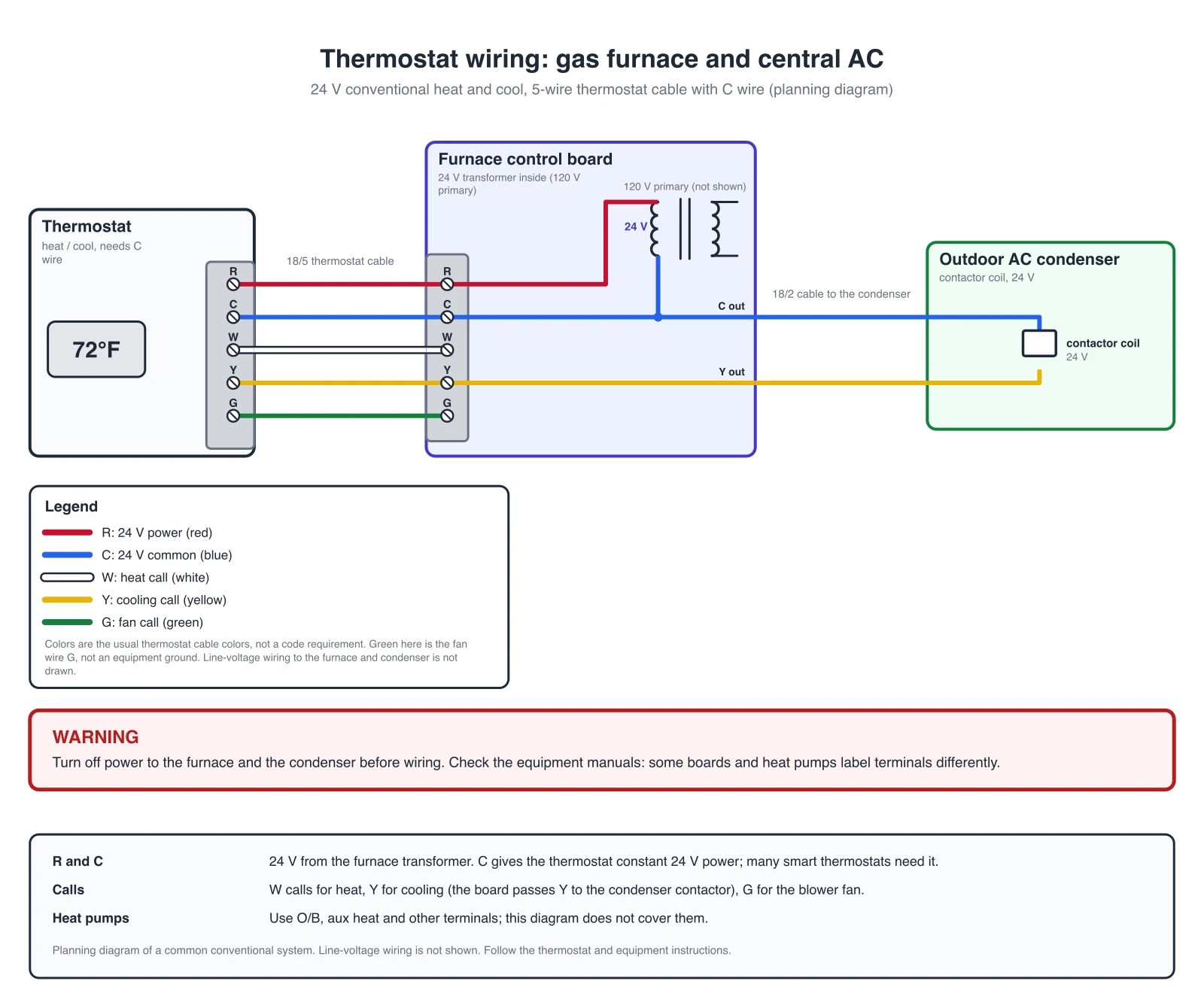
This is the wiring cousin: R / Y / G / W plus C, a 24 V transformer, a contactor coil. An exact diagram, drawn in code, of a conventional gas furnace and central AC. It does not show refrigerant state or mixed-air economizer flow, and heat pumps use other terminals. Use it only when the job is electrical.
Step 1 — Write the one sentence the drawing must prove
Bad brief: “HVAC system.”
Usable briefs:
- “Packaged rooftop unit serving one zone: OA damper, DX coil, supply fan, return, exhaust. Show SA / RA / EA / OA arrows and filter.”
- “Air-source split system: compressor, outdoor coil, TXV, indoor coil, liquid and suction lines. Label discharge, liquid, suction.”
- “Primary-secondary chilled water: chiller, primary pump, decoupler, secondary pump, AHU coil, three-way valve.”
If you cannot say which of the four drawing types you are on, you will get a collage of a thermostat, a duct, and a snowflake.
A worked pair:
- Keep: “AHU-1, single zone. OA damper into a filter, mixed air with RA, CHW coil, supply fan, SA to the zone, EA relief. Arrows on every air stream. No thermostat.”
- Rewrite: “Make a full HVAC system with wiring, ducts on a floor plan, and the refrigeration cycle.” That is three drawings. Split them or the generator will invent a fourth.
Step 2 — Freeze names before you draw
Use the abbreviations the shop already uses. A typical English legend (always confirm on that project’s sheet 1):
- OA / SA / RA / EA — outside, supply, return, exhaust air
- AHU / RTU / FCU / VAV / ERV — air handler, rooftop, fan coil, variable-air-volume box, energy recovery
- CDU — condensing unit
- CHW / HHWS / CW — chilled water, heating hot water supply, condenser water
Tag equipment the same way a schedule would: AHU-1, CH-1, P-1. If two coils exist, say CCH (cooling) and HCH (heating) or the project’s names. A diagram that says “coil” twice is a guessing game.
Step 3 — Draw flow, then boxes
For air-side: start at the outdoor-air intake. Walk the air through filter → optional heat recovery → mixed-air plenum → coils → fan → supply. Show return joining mixed air if that is the truth. Arrows are the drawing. Boxes are labels.
For refrigerant: start at the compressor discharge. High-pressure vapor to the condenser, liquid through the expansion device, low-pressure vapor back on the suction line. This is the vapor-compression loop every textbook draws; ASHRAE fundamentals still treat it as the core picture. Color or line weight can mark high vs low side — only if you put a legend on the same sheet. Do not invent PSI values you did not measure.
For hydronic: pumps first, then the source (chiller / boiler / tower), then the coil, then the return. Show the decoupler or buffer tank if the plant has one. A straight line from “chiller” to “building” is a poster, not a schematic.
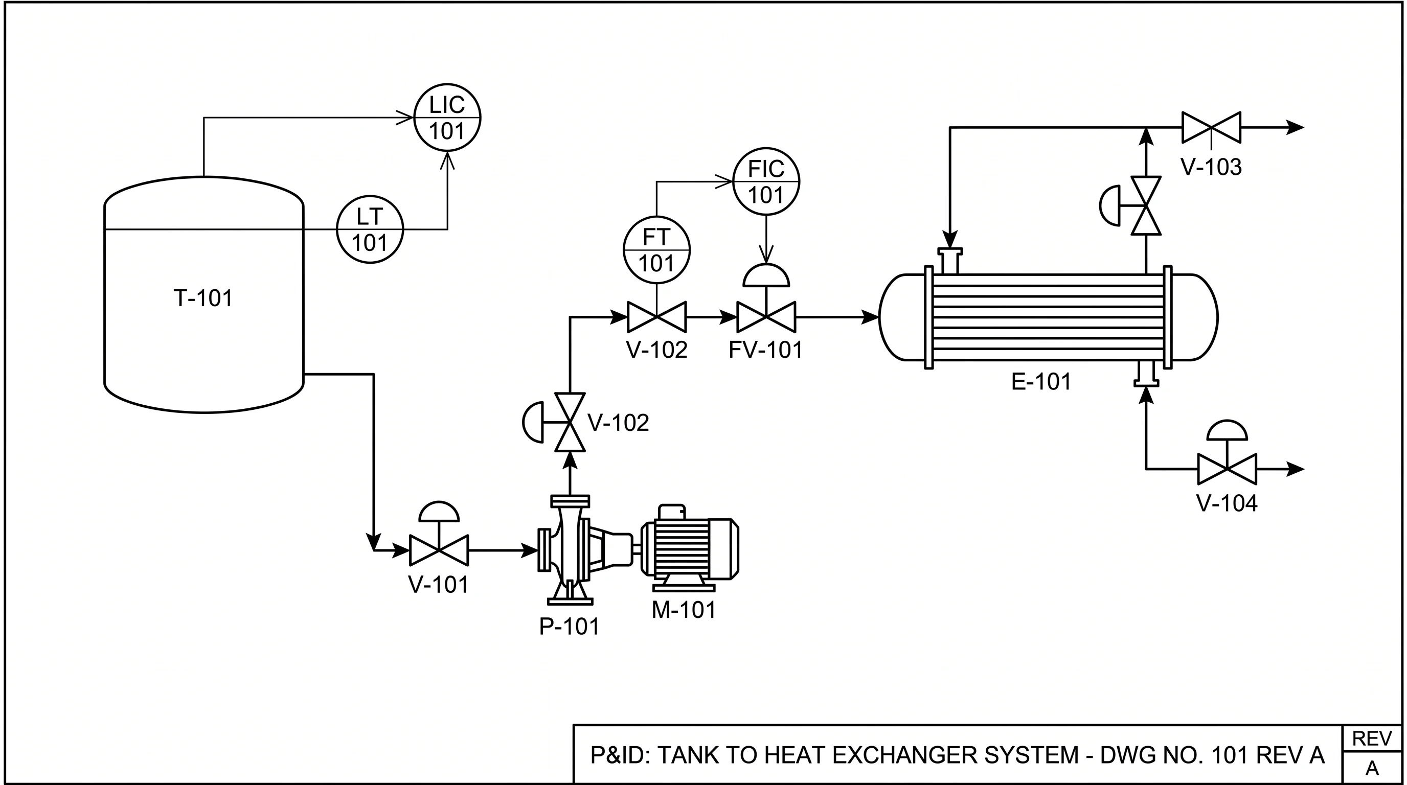
P&ID Maker
When the HVAC plant is really a process: valves, transmitters, and tagged instruments on hydronic loops.
Step 4 — Label streams, not adjectives
Every line that changes state needs a name: SA, liquid, CHWS, hot gas. “Cold air” is not a label. Pressure and temperature belong on the sheet only when they are design or measured values. A generated picture that writes “350 PSI” because the prompt sounded industrial is a liability.
Keep one symbol language. Training slides can use simple rectangles. A shop schematic should follow the project legend or a published HVAC symbol sheet — see a typical HVAC symbol overview and then the legend on your drawing set. There is no universal clip-art AHU that matches every contractor.
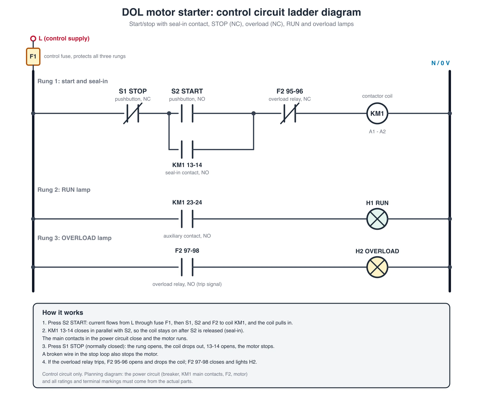
An exact motor-starter control circuit, drawn in code. Controls and power landings stay on a wiring or elementary diagram like this one. If your HVAC schematic starts growing PLC I/O, split the page. One sheet, one question.
Step 5 — Say what the drawing is not
Put a one-line note on student and client slides:
- “Schematic, NTS. Not for construction.”
- “Training figure. Verify against the manufacturer’s installation diagram before service.”
A pretty loop does not size a TXV and does not replace the unit’s wiring label. EdrawMax and similar tools rank for “HVAC diagram” because people want a picture. Permit work still goes through the engineer of record.
A short prompt that does not wander into wiring
Use this shape on the HVAC generator (or, until that page is live, a careful prompt on the schematic maker — knowing that page is built for lab apparatus, not rooftop units):
Air-side schematic of a single-zone AHU. Left to right: OA intake with damper, filter bank, mixed-air plenum joining RA, cooling coil, heating coil, supply fan, SA duct to the zone. Show RA path back to the mixed-air plenum and an EA relief. Label OA, SA, RA, EA, AHU-1. White background, flat schematic, no thermostat terminals, no wire colors, no title block.
Then change only the sentence that is false for your plant. If the real unit has no heating coil, delete that box instead of leaving a red rectangle “for completeness.” Extra equipment the plant does not own is how trainees troubleshoot a ghost.
Wiring Diagram Maker
Thermostat letters, 24 V transformers, contactors, and panel landings — the electrical document.
Refrigeration cycle vs “the HVAC diagram”
Search volume piles onto refrigeration cycle diagram because every intro class draws compressor–condenser–expansion–evaporator. That loop is one HVAC schematic, not the whole plant. A rooftop unit also has air-side dampers and often a gas heat exchanger. A chiller plant may not show refrigerant at all on the air-side sheet.
If the assignment is “label the four components of the vapor-compression cycle,” draw only those four plus the two pressures. If the assignment is “show how the AHU conditions mixed air,” do not drop a compressor in the corner for decoration.
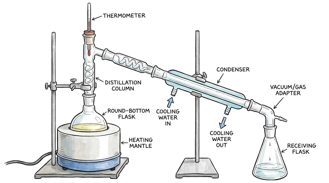
The lab schematic maker draws flasks and condensers. Do not use it as a substitute rooftop-unit library. Different symbols, different reader.
Where this sits next to other ConceptViz pages
- System / refrigerant / air-side picture →
/tools/hvac-diagram-generator(this article’s primary tool). - Thermostat and power wiring → wiring diagram maker and how to make a wiring diagram.
- Tagged hydronic instruments → P&ID maker.
- Building electrical one-line → single-line diagram generator.
- Lab glassware → schematic diagram maker.
Mistakes that waste a revision
Thermostat alphabet on an air-side sheet. R and Y are electrical. SA and OA are air. Pick one language.
No arrows. A box labeled “AHU” with four unlabeled pipes is clip art.
Invented setpoints. If you did not read the schedule, do not print 55 °F supply air.
One drawing that tries to be plan + schematic + wiring. Split it. Field techs will thank you.
Using a generator as the as-built. Manufacturer PDFs and the stamped set still win.
Frequently Asked Questions
What is an HVAC diagram?
Usually a system schematic: how air, refrigerant, or water moves through equipment. It is not automatically a wiring diagram or a floor plan. Name the stream you are drawing before you start.
What is the difference between an HVAC schematic and HVAC wiring?
A schematic shows function and flow (OA into an AHU, refrigerant around a DX loop). Wiring shows terminals and conductors (R, C, Y, G, W, contactors). Use different pages for those jobs.
How do I draw a refrigeration cycle diagram?
Compressor, condenser, expansion device, evaporator, in that order, with discharge, liquid, and suction labeled. Do not add thermostat letters. Do not invent pressures you did not measure.
Can I use this instead of AutoCAD or Revit?
No for permit sets, coordination, or BIM. Yes for a class slide, a service conversation, or a first picture of flow. Construction documents stay with the engineer of record.
Where do I make a thermostat wiring diagram?
On the wiring diagram maker, or from the manufacturer’s label. This article will not generate Honeywell pinouts. Those searches are model-specific look-ups.
What abbreviations should I use?
Match the project legend. Common English tags are OA/SA/RA/EA, AHU, RTU, FCU, VAV, CHW, and equipment IDs like AHU-1. Do not mix two contractors’ slang on one sheet.
Is a P&ID the same as an HVAC schematic?
A hydronic HVAC schematic can grow into a P&ID when you add instrument bubbles, control valves, and line numbers. If you need ISA tags, use the P&ID tool. If you only need OA/SA/RA arrows, stay on the air-side schematic.
Can I trust numbers on a generated HVAC diagram?
No. Treat generated labels as placeholders. Copy design values from the schedule or measured values from gauges. A wrong CFM or PSI on a training slide still teaches the wrong plant.
Bottom line
One sheet, one stream. Air, refrigerant, water, or wires — not all four. Write the sentence the drawing must prove, tag the equipment, draw arrows, then generate a draft you can correct.
For the system picture use the HVAC diagram generator. For landings and thermostat letters use the wiring diagram maker. For a stamped set, stay in CAD.
Categorías
Más Publicaciones

15 Illustration and Infographic Design Styles Explained (2026)
Explore 15 illustration and infographic design styles with examples: flat, isometric, 3D, hand-drawn, minimalist, vector, cartoon, line art and more.

Best AI Scientific Illustration Tools and Software (2026)
Scientific illustration software for each paper figure step: BioRender, Prism, Illustrator, Inkscape, and AI tools. Prices checked October 2026.
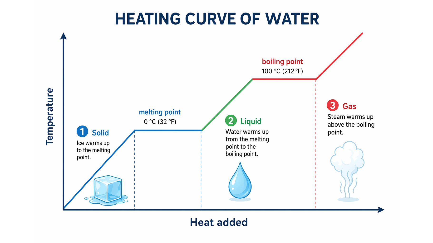
Heating Curve of Water Explained: The 5 Stages
Understand the heating curve of water step by step: what the axes mean, why the plateaus are flat, and how specific and latent heat shape each stage.