")
How to Create Circuit Diagrams Online: Free Tools & Step-by-Step Guide (2026)
Learn how to draw circuit diagrams online for free. Compare top circuit diagram makers and follow our step-by-step guide to create professional electrical diagrams.
Circuit diagrams are the universal language of electronics and electrical engineering. Whether you are a physics student completing a lab report, an engineer designing a power supply, or a teacher preparing classroom materials, knowing how to draw accurate circuit diagrams is an essential skill.
This guide walks you through everything you need to create professional circuit diagrams online for free--from understanding standard symbols and conventions to using the best tools available in 2026.
Circuit Diagram Maker
Create professional circuit diagrams and electrical schematics from text descriptions. Supports resistors, capacitors, transistors, and more.
Try it free →What Is a Circuit Diagram?
A circuit diagram (also called a schematic diagram or electrical schematic) is a simplified graphical representation of an electrical circuit. It uses standardized symbols to represent components such as resistors, capacitors, batteries, switches, and wires, and shows how those components are connected.
Circuit diagrams are not meant to show the physical layout of components. Instead, they focus on the logical connections and electrical relationships within the circuit.
Types of Circuit Diagrams
| Type | Description | Best For |
|---|---|---|
| Schematic diagram | Uses standard symbols; shows electrical connections logically | Engineering design, textbooks, lab reports |
| Pictorial diagram | Shows realistic component illustrations | Hobbyist guides, assembly instructions |
| Wiring diagram | Shows physical connections and wire routing | Electricians, installation guides |
| Block diagram | High-level overview with blocks for subsystems | System architecture, presentations |
This guide focuses on schematic diagrams, the most common type used in education and engineering.
Essential Circuit Diagram Symbols
Before drawing a circuit, you need to understand the standard symbols. The two major standards are IEEE/ANSI (used primarily in the United States) and IEC (used internationally in Europe and most other regions).
Passive Components
| Component | IEEE/ANSI Symbol | IEC Symbol | Function |
|---|---|---|---|
| Resistor | Zig-zag line | Rectangle | Limits current flow |
| Capacitor | Two parallel lines | Two parallel lines | Stores electrical charge |
| Inductor | Coiled line | Coiled line | Stores energy in magnetic field |
| Fuse | S-shaped curve in a rectangle | Rectangle with wire | Protects circuit from overcurrent |
Active Components
| Component | Symbol Description | Function |
|---|---|---|
| Battery | Long and short parallel lines (+ and -) | Provides DC voltage |
| AC Source | Circle with sine wave | Provides AC voltage |
| Diode | Triangle with line | Allows current in one direction |
| LED | Diode symbol with arrows | Emits light when current flows |
| Transistor (NPN) | Three-terminal symbol with arrow out | Amplifies or switches signals |
| Transistor (PNP) | Three-terminal symbol with arrow in | Amplifies or switches signals |
Switches and Connections
| Component | Symbol Description | Function |
|---|---|---|
| SPST Switch | Break in line with lever | Opens or closes a circuit |
| SPDT Switch | One input, two output contacts | Selects between two paths |
| Wire | Straight line | Connects components |
| Wire junction | Dot at intersection | Indicates connected wires |
| No connection | Crossing lines without dot | Wires cross but do not connect |
| Ground | Descending horizontal lines | Reference voltage point |
Logic Gates (Digital Circuits)
| Gate | Function | Truth Summary |
|---|---|---|
| AND | Output high only if all inputs high | 1 AND 1 = 1 |
| OR | Output high if any input high | 0 OR 1 = 1 |
| NOT | Inverts input | NOT 1 = 0 |
| NAND | AND followed by NOT | 1 NAND 1 = 0 |
| NOR | OR followed by NOT | 0 NOR 0 = 1 |
| XOR | Output high if inputs differ | 1 XOR 0 = 1 |
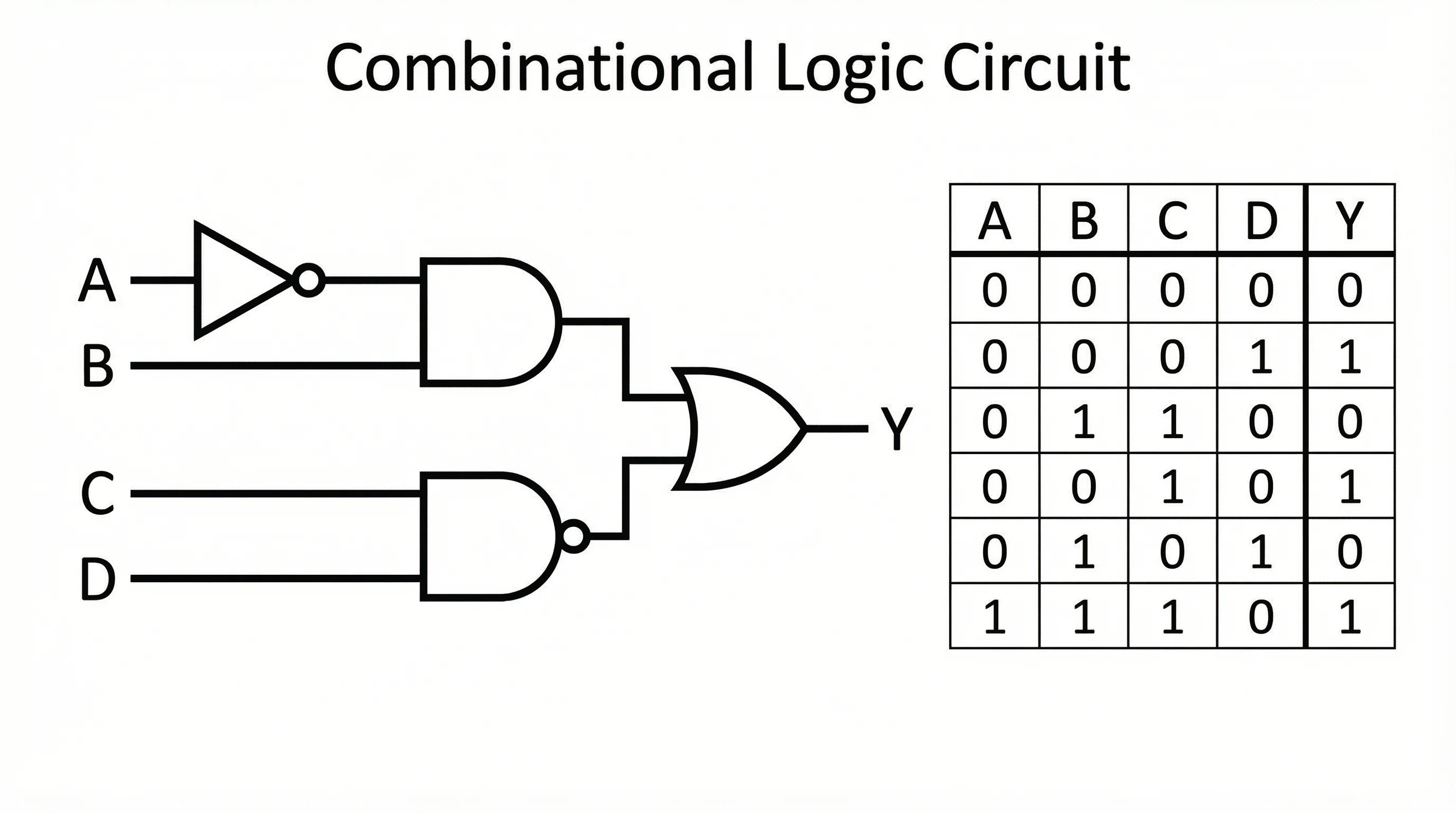
A digital logic circuit showing multiple gate types and their interconnections
Step-by-Step: How to Create a Circuit Diagram Online
Follow this process to create a clean, accurate circuit diagram using any online tool.
Step 1: Plan Your Circuit
Before opening any tool, sketch the circuit on paper or define it conceptually:
- What does the circuit do? (e.g., LED driver, voltage divider, RC filter)
- What components are needed? (list every resistor, capacitor, IC, etc.)
- What are the input and output? (power supply voltage, signal source, load)
- What values do components have? (resistance in ohms, capacitance in farads)
Step 2: Choose Your Tool
Select an online circuit diagram maker based on your needs (see the comparison table below). For quick educational diagrams, a simple schematic editor works best. For simulation, choose a tool with SPICE capabilities.
Step 3: Place Components
Start by placing the main components on the canvas:
- Place the power source (battery or power supply) on the left side
- Add the main components (resistors, capacitors, ICs) in the signal flow direction
- Place the output or load on the right side
- Add switches and protection components (fuses, diodes) where needed
Step 4: Connect with Wires
Draw wires to connect components according to your circuit design:
- Use straight horizontal and vertical lines (avoid diagonal wires)
- Add junction dots where wires intentionally connect at crossings
- Keep wires as short as possible to reduce visual clutter
- Avoid unnecessary wire crossings by rearranging components
Step 5: Add Labels and Values
Label every component with:
- Reference designator (R1, R2, C1, C2, U1, etc.)
- Component value (10k ohm, 100uF, LM7805, etc.)
- Net names for important signals (VCC, GND, CLK, DATA)
- Pin numbers for ICs and connectors
Step 6: Verify and Export
Before finalizing:
- Check continuity -- trace every path from power to ground
- Verify polarity -- ensure electrolytic capacitors, diodes, and ICs face the correct direction
- Review values -- confirm all component values match your design calculations
- Export in your preferred format (PNG for reports, SVG for scalable graphics, PDF for printing)
Common Circuit Diagram Examples
Here are several example circuits that cover the most common use cases in education and engineering.
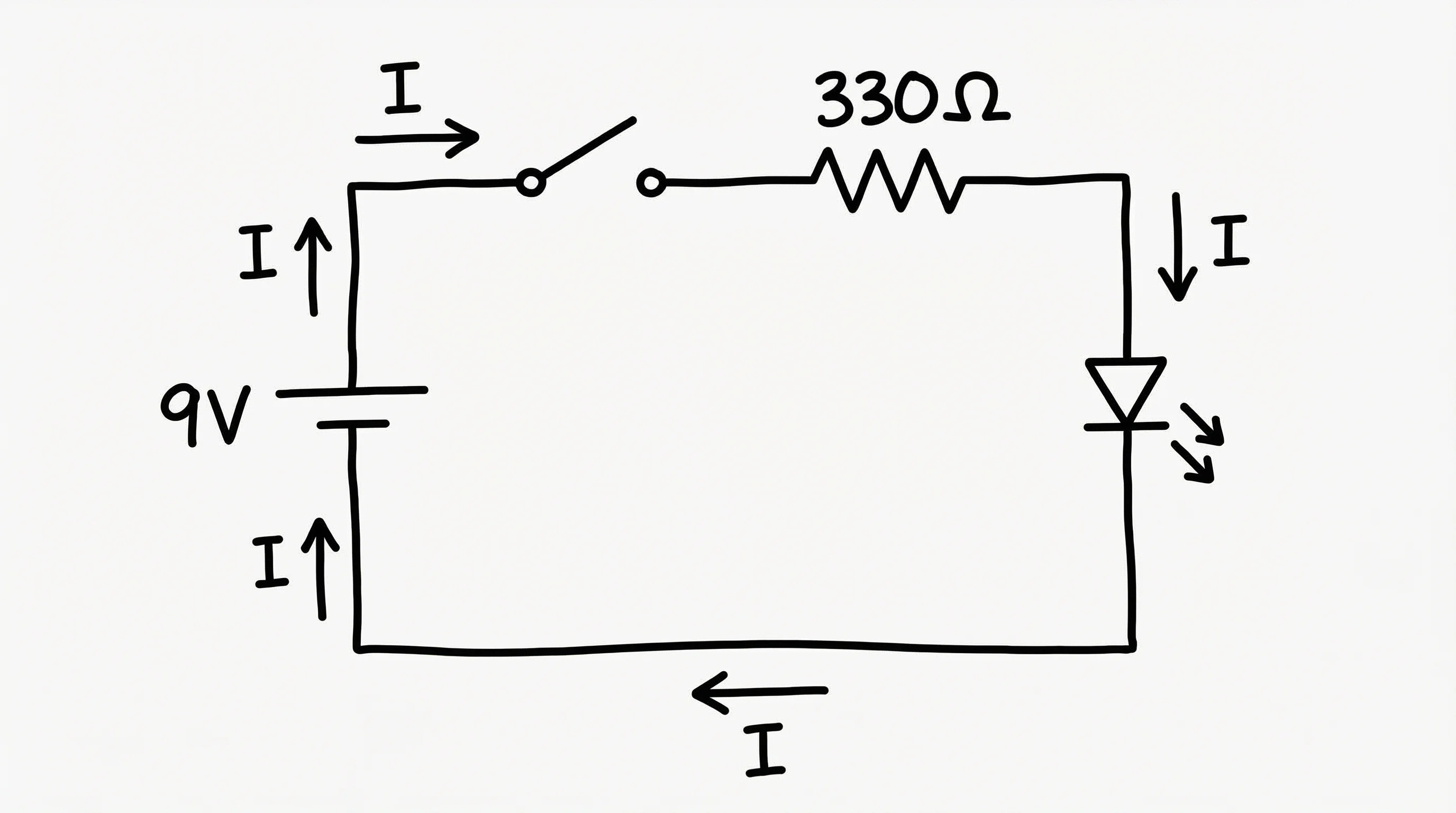
Simple DC Circuit
The most fundamental circuit: a battery connected to a resistor through a switch.
A basic DC circuit demonstrating Ohm's law with a battery, switch, and resistor
This circuit is the starting point for teaching Ohm's law (V = IR) and is found in every introductory physics course.
Series and Parallel Circuits
Understanding series and parallel connections is critical for circuit analysis.
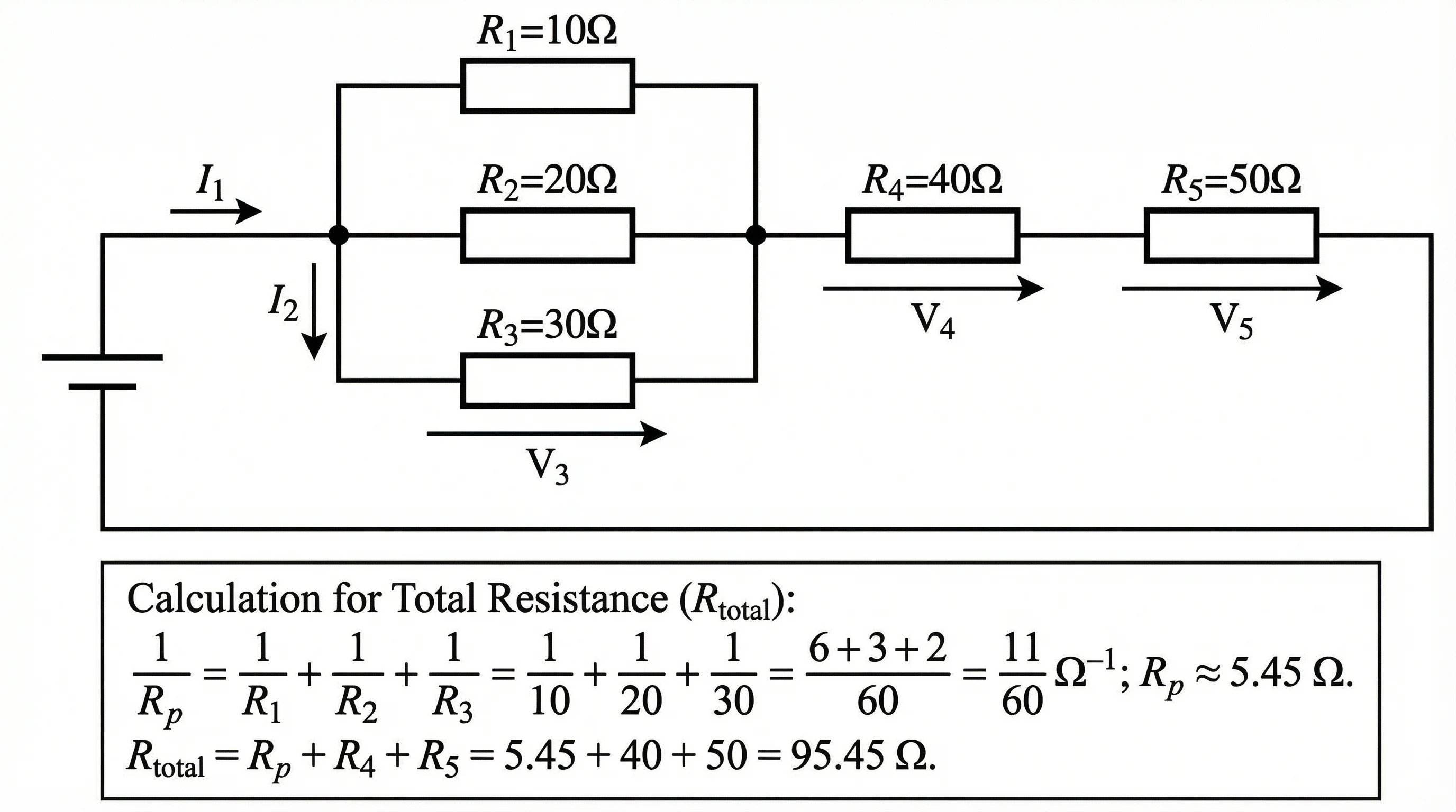
A circuit showing both series and parallel resistor configurations
Series circuit: Components share the same current. Total resistance = R1 + R2 + R3.
Parallel circuit: Components share the same voltage. Total resistance = 1/(1/R1 + 1/R2 + 1/R3).
RC Circuit (Resistor-Capacitor)
RC circuits are fundamental to signal filtering and timing applications.
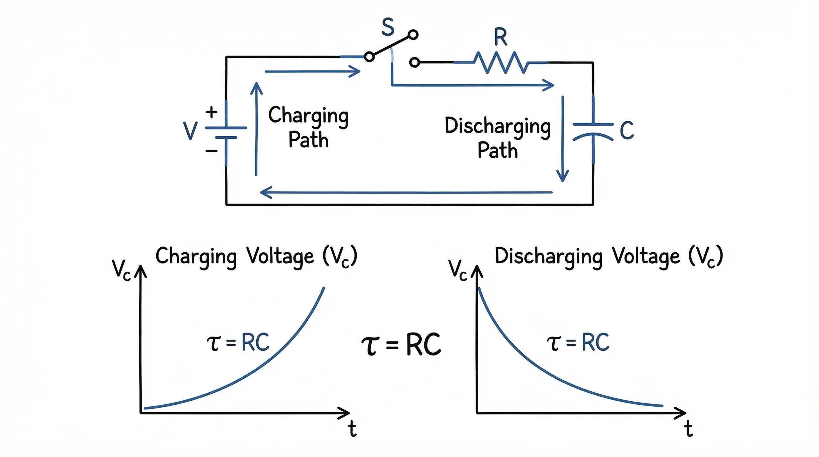
An RC circuit used for low-pass filtering and time-delay applications
The time constant (tau = RC) determines how quickly the capacitor charges or discharges. RC circuits are used in audio filters, debouncing switches, and timer circuits.
Wheatstone Bridge
The Wheatstone bridge is a precision measurement circuit used to determine unknown resistance values.
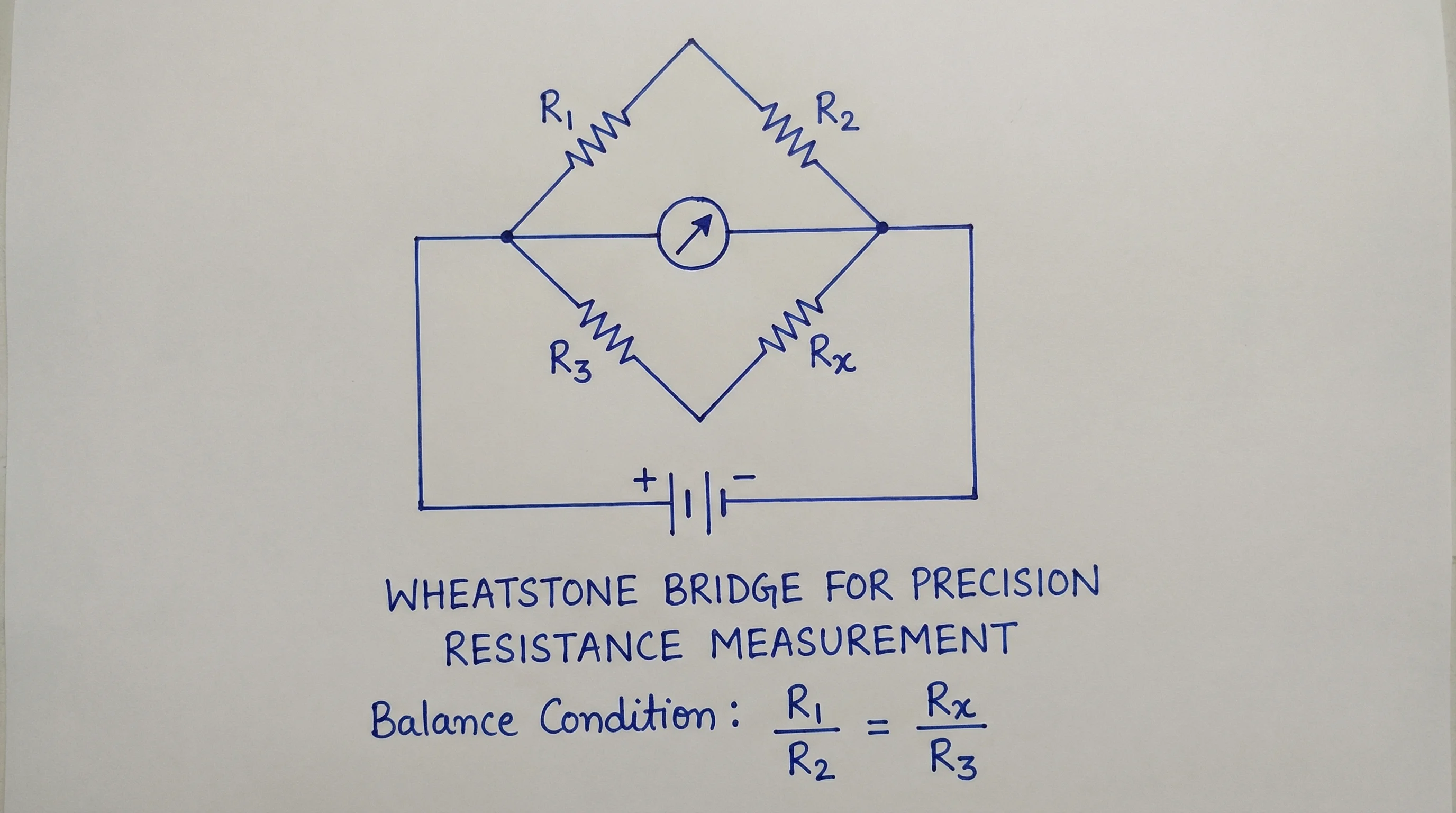
A Wheatstone bridge circuit for precise resistance measurement
When the bridge is balanced (V_bridge = 0), the unknown resistance can be calculated from the three known resistances.
Transistor Amplifier Circuit
Transistor circuits form the basis of analog amplifier design.
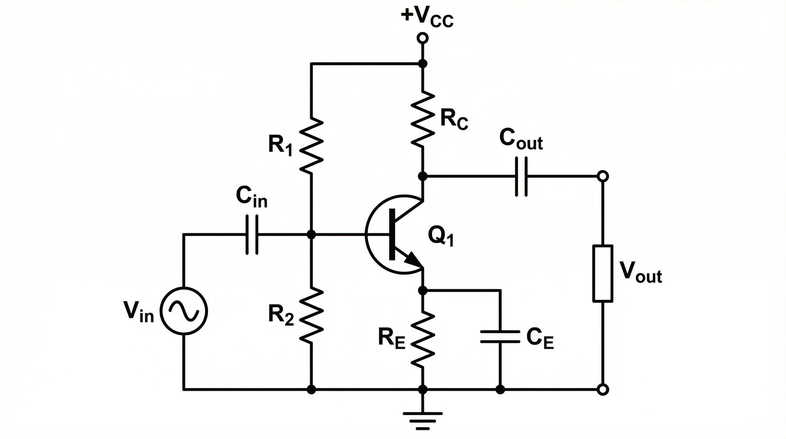
A common-emitter transistor amplifier circuit with biasing resistors
Best Free Circuit Diagram Tools Compared (2026)
Here is a detailed comparison of the best free online tools for creating circuit diagrams.
| Tool | Best For | Simulation | Symbols | Export Formats | Price |
|---|---|---|---|---|---|
| ConceptViz | AI-powered text-to-circuit | No | Standard IEEE/IEC | PNG, SVG | Free tier available |
| Falstad Circuit Simulator | Interactive simulation | Yes (real-time) | Basic components | PNG, text | Free |
| CircuitLab | Education and quick schematics | Yes (SPICE) | Extensive library | PNG, PDF, SVG | Free tier (10 circuits) |
| EasyEDA | PCB design pipeline | Yes (SPICE) | 1M+ component library | PNG, PDF, Gerber | Free |
| Tinkercad Circuits | Beginners and Arduino | Yes (visual) | Common components | PNG, link sharing | Free |
| KiCad | Professional PCB design | Yes (ngspice) | Comprehensive | PDF, SVG, Gerber | Free & open source |
| LTspice | Analog circuit simulation | Yes (SPICE) | Analog focus | PDF, clipboard | Free |
Choosing the Right Tool
- For physics homework and lab reports: Tinkercad Circuits or ConceptViz -- simple, visual, and fast
- For electronics courses: CircuitLab or Falstad -- simulation helps verify understanding
- For engineering projects: EasyEDA or KiCad -- full pipeline from schematic to PCB
- For analog design: LTspice -- industry-standard SPICE simulation engine
- For quick diagrams from text: ConceptViz -- describe your circuit and get a professional schematic instantly
Circuit Diagram Tips for Physics Students
If you are creating circuit diagrams for class assignments, lab reports, or exams, follow these tips to earn full marks.
1. Use Standard Symbols
Always use recognized IEEE or IEC symbols. Do not draw creative interpretations of components. Your teacher expects to see standard resistor zig-zags (or rectangles), standard capacitor plates, and standard battery terminals.
2. Label Everything
Every component should have a reference designator (R1, C1, L1) and a value (100 ohm, 47uF). Every node should have a voltage label where relevant. Missing labels is the most common reason students lose points on circuit diagram assignments.
3. Show Current Direction
Use arrows to indicate conventional current direction (from positive to negative terminal). This helps verify your circuit analysis using Kirchhoff's current law (KCL).
4. Keep It Clean
- Align components horizontally and vertically
- Use consistent spacing between components
- Avoid diagonal wires
- Place the power source on the left, the load on the right
- Ground connections should point downward
5. Include Calculations
For lab reports, annotate your circuit diagram with calculated values:
- Expected voltage drops across components
- Current through each branch
- Total power dissipation
- Component power ratings
6. Digital vs Analog Conventions
- Analog circuits: Show ground symbols, label voltage rails, indicate current paths
- Digital circuits: Show logic levels (HIGH/LOW), label clock signals, indicate data flow direction
Circuit Diagram Best Practices for Engineers
Professional engineers follow additional conventions to ensure circuit diagrams are maintainable and unambiguous.
Hierarchical Design
For complex circuits, use a hierarchical approach:
- Top-level block diagram -- shows major subsystems and their connections
- Subsystem schematics -- detailed circuit for each block
- Component details -- individual component specifications
Net Naming Conventions
Adopt consistent net naming:
VCC,VDDfor positive power railsGND,VSSfor ground references- Descriptive signal names:
CLK_100MHz,DATA_IN,RESET_N(active-low suffix) - Bus notation:
ADDR[15:0],DATA[7:0]
Design for Manufacturability
If your schematic will become a PCB:
- Include decoupling capacitors near every IC power pin
- Add test points for critical signals
- Show mounting holes and mechanical constraints
- Reference your bill of materials (BOM)
Frequently Asked Questions
What is the best free circuit diagram maker for students?
For students, Tinkercad Circuits and ConceptViz are the best starting points. Tinkercad offers a visual drag-and-drop interface with built-in simulation, making it ideal for beginners. ConceptViz lets you describe circuits in plain text and generates professional schematics instantly. For more advanced needs, CircuitLab and Falstad offer free tiers with simulation capabilities.
What is the difference between a circuit diagram and a wiring diagram?
A circuit diagram (schematic) uses standard symbols to show the electrical connections and logic of a circuit without regard to physical layout. A wiring diagram shows the physical routing of wires and the actual placement of components, making it useful for electricians and technicians during installation. Schematics are used for design and analysis; wiring diagrams are used for construction and maintenance.
Which standard should I use for circuit symbols, IEEE or IEC?
Use the standard expected by your audience. In the United States, IEEE/ANSI symbols are standard (zig-zag resistors, for example). In Europe and most international contexts, IEC symbols are preferred (rectangular resistors). In educational settings, follow whatever your textbook or instructor uses. Most online tools support both standards.
Can I simulate my circuit diagram online for free?
Yes. Falstad Circuit Simulator provides real-time interactive simulation entirely in the browser for free. CircuitLab offers SPICE simulation with a free tier. Tinkercad Circuits supports visual simulation with Arduino integration. For professional analog simulation, LTspice from Analog Devices is free to download and use.
How do I draw a circuit diagram for a physics lab report?
Start by identifying all components in your physical circuit. Choose an online tool (ConceptViz, CircuitLab, or draw.io). Place components using standard symbols, connect them with horizontal and vertical wires, add reference designators (R1, C1) and values (100 ohm, 10uF), label all voltage sources and ground connections, and export as PNG or PDF for your report.
What is the difference between series and parallel circuits?
In a series circuit, components are connected end-to-end so the same current flows through each component. Total resistance is the sum of individual resistances. In a parallel circuit, components are connected across the same two nodes so they share the same voltage. Total resistance is calculated using the reciprocal formula: 1/R_total = 1/R1 + 1/R2 + 1/R3.
How do I export my circuit diagram for a research paper?
For research papers, export your circuit diagram as a vector format (SVG or PDF) for the best print quality. Most journals accept PDF, EPS, or high-resolution PNG (at least 300 DPI). Ensure all text labels are legible at the final print size, use consistent line weights, and follow the journal's figure guidelines for dimensions and file size.
Can I create circuit diagrams on my phone or tablet?
Yes. Web-based tools like ConceptViz, Falstad, and CircuitLab work in mobile browsers. For dedicated mobile apps, iCircuit (iOS) and EveryCircuit (Android/iOS) offer touch-optimized circuit drawing and simulation. However, for complex diagrams, a desktop or laptop with a larger screen is recommended for precision.
Conclusion
Creating circuit diagrams online has never been easier. With free tools ranging from simple schematic editors to full SPICE simulators, you can produce professional-quality diagrams for any purpose--from a physics homework assignment to a production PCB design.
Key takeaways:
- Learn the standard symbols -- IEEE for US audiences, IEC for international work
- Plan before you draw -- list all components, connections, and values before opening your tool
- Follow conventions -- horizontal/vertical wires, consistent labels, proper junction dots
- Choose the right tool -- simulators for verification, simple editors for documentation, AI tools for speed
- Label everything -- reference designators, values, net names, and voltage levels
- Verify before exporting -- check continuity, polarity, and component values
Whether you are a student learning Ohm's law or an engineer designing your next product, a well-drawn circuit diagram is the foundation of clear technical communication.
Additional Resources
- How to Make Scientific Diagrams for Research Papers
- Scientific Illustration Complete Beginners Guide
- Scientific Color Palette for Research Papers and Posters
- How to Design Infographics for Scientists
Ready to create your circuit diagram? Try ConceptViz's Circuit Diagram Maker to generate professional schematics from text descriptions instantly.
分類
更多文章

Protein Structure: The 4 Levels Explained Simply
Protein structure made simple: the four levels (primary, secondary, tertiary, quaternary), the bonds that stabilize each, and why structure decides function.

Best AI Scientific Illustration Tools in 2026: Complete Guide
Compare the best AI-powered scientific illustration tools for researchers in 2026. From BioRender to ConceptViz, find the right tool for publication-quality scientific figures.
")
How to Create a Network Diagram: Types, Symbols & Step-by-Step Guide (2026)
Learn how to create network diagrams for IT infrastructure. Covers logical vs physical diagrams, standard symbols, topology types, and real-world examples.